Linkage type tool magazine tool changing device

A tool changing device and linkage technology, which is applied in positioning device, clamping, supporting and other directions, can solve problems such as elastic fatigue, affecting accuracy, and easy fatigue of torsion springs, etc., so as to achieve not easy elastic fatigue, fast tool changing response, and stable noise Effect

Inactive Publication Date: 2011-10-05
PRECISION MACHINERY RES & DEV CENT
View PDF6 Cites 6 Cited by
  • Summary
  • Abstract
  • Description
  • Claims
  • Application Information

AI Technical Summary

Problems solved by technology

[0004] 1. When the torsion spring is continuously activated, it is prone to elastic fatigue or even breakage, and then cannot quickly return to the predetermined position during the rapid rise and fall of the spindle, so the tool change speed cannot be increased, which affects the efficiency of tool change ;In addition, when the torsion spring is fatigued, the alignment of the jaws will be different each time the tool is changed, resulting in an error in the alignment between the jaws and the spindle
[0005] 2. The torsion spring needs a large load force, so the friction generated by each action and the error between the jaw and the spindle will cause obvious noise
[0011] The above-mentioned structure utilizes the roller 26 to be embedded in the track 24, and utilizes the shape of the track 24 to limit and change the swing angle of the knife seat 21; it can overcome Figure 1a The torsion spring of the structure shown is prone to lack of fatigue, but since the entire tool magazine 21 needs to swing every time a tool is changed, the pivot 27 and the stand column are easily deformed, which in turn affects the accuracy of machining

Method used


Image

  • Linkage type tool magazine tool changing device
  • Linkage type tool magazine tool changing device
  • Linkage type tool magazine tool changing device

Examples


Embodiment Construction

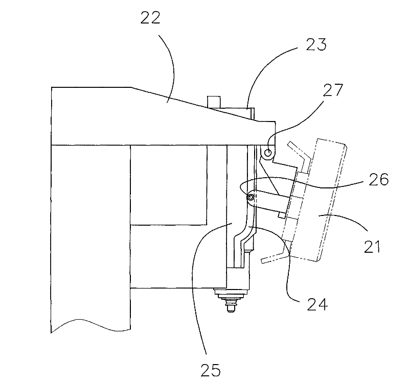
[0059] see image 3 , the figure shows that the spindle headstock 30 of the machine tool is adjacent to a tool magazine 40; the tool magazine 40 has a rotating disk 41, and several tool clamping arms 42 are set on the rotating disk 41 (a tool clamping arm is shown in the figure) ; In particular, the tool clamp arm 42 has a base 43 and a swing arm 44, wherein the base 43 is fixed on the rotary cutter head 41, and the swing arm 44 is swingably configured on the base 43; there is also a torsion spring 45 It is arranged on the swing arm 44 of the tool holder arm 42 , one end of which can be fixed to the base 43 , and the other end can be fixed to the swing arm 44 . One end of the above-mentioned tool clamp arm 42 is opposite to the spindle headstock 30 and is used to clamp a tool handle (not shown); the tool clamp arm 42 is further matched with a guide plate 50 so that the swing arm 44 of the tool clamp arm 42 can swing to The tool handle is inserted into or withdrawn from the sp...


PUM


Abstract

The invention relates to a linkage type tool magazine tool changing device which is arranged between a tool magazine and a spindle headstock and is used for holding one end, which is inserted into or taken out from the spindle headstock, of a tool holder. The device comprises a guide plate, a first rail, a tool clamping arm and a first idler wheel, wherein the guide plate is arranged on the spindle headstock; the first rail is formed on the guide plate and is constructed into a slot channel; the tool clamping arm is arranged on the tool magazine and is provided with a swing arm capable of swinging; one end of the swing arm is opposite to the spindle headstock; the first idler wheel is rotatably arranged on the swing arm of the tool clamping arm and rotates after being embedded into the first rail; and when the spindle headstock linearly displaces, the first idler wheel rotates and moves along the first rail and the swing arm swings along with the displacement of the first idler wheel relative to the first rail, thereby changing a tool by holding the tool holder or separating from the tool holder. The linkage type tool magazine tool changing device has the beneficial effects that the load is small, the tool-changing response is quick and stable, the noise is low, a torsion spring has less possibility of being subjected to elastic fatigue, and the device is durable.

Description

technical field [0001] The invention relates to a tool changing device, in particular to a tool changing device which works quickly, stably and is durable. Background technique [0002] The traditional tool change mode of the tool magazine is that a rotary cutter head is driven by an indexer to rotate a predetermined angle to the position, and then the spindle lowers the jaws on its nose to grab the tool, and then continues to descend so that the jaws are pushed outward; when When the jaws are pushed away, the torsion spring configured at the root is deformed to store an elastic potential energy; when the main shaft rises again, the originally pushed outward jaws return to their original positions driven by the elastic potential energy. From the above, the active force of the torsion spring is the main active force for driving the jaws to reset and swing. [0003] However, this mechanism has the following disadvantages: [0004] 1. When the torsion spring is continuously a...

Claims


Application Information

Patent Timeline
IPC IPC(8): B23Q3/155
Inventor 黄俊嘉刘宗志
Owner PRECISION MACHINERY RES & DEV CENT
Why Eureka
Try Eureka