Concrete spreader

A technology of placing machine and concrete, which is applied to unloading devices, ceramic molding machines, manufacturing tools, etc., can solve the problem that the concrete is easily scattered outside the steel mold of the pipe pile and the mold clamping part, and the concrete supply and energy consumption cannot be effectively controlled. The problem of high wear and tear of Jiaolong can achieve the effect of small power, low cost of use and small viscous effect.

Active Publication Date: 2011-10-05
宁波中淳高科股份有限公司
View PDF0 Cites 3 Cited by
  • Summary
  • Abstract
  • Description
  • Claims
  • Application Information

AI Technical Summary

Problems solved by technology

[0002] At present, there are two types of concrete placing machines in the prior art, one is an ordinary curtain-type concrete placing machine, and the other is a dragon-type placing machine; Closing to achieve or stop the action of material distribution, the concrete in the hopper will fall by its own gravity during material distribution, if you want to increase the amount of material distribution, you need to increase the opening degree of the discharge door, but this will easily make the opening of the discharge port If the thickness is greater than the diameter of the steel formwork for pipe piles, the falling concrete is easily scattered outside the steel formwork for pipe piles and the mold closing part. It is necessary to carefully clean the steel formwork for pipe piles before closing the molds. There are problems that the blanking is not dense enough, the distribution efficiency is low, and the supply of concrete cannot be effectively controlled; the latter is equipped with a horizontal dragon under the hopper, that is, a screw-type feeding device, and the concrete is sent to the outlet through the dragon. Although the distribution machine with this structure can accurately control the amount of blanking, the concrete will fall by its own gravity after reaching the outlet, so the problem of loose blanking has not been solved. Due to the characteristics of hysteresis, the large power required for the rotation of the dragon, the energy consumption and the wear of the dragon are high, which makes the use cost higher

Method used


Image

  • Concrete spreader
  • Concrete spreader
  • Concrete spreader

Examples


Embodiment Construction

[0017] The present invention will be further described below in conjunction with the accompanying drawings and specific embodiments.

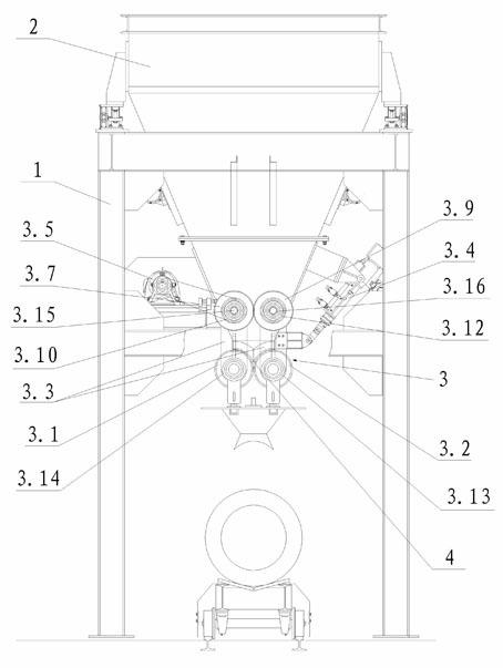
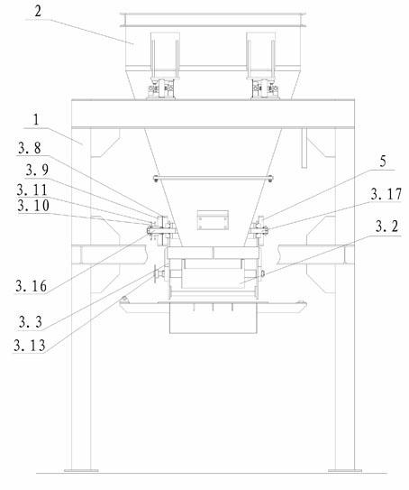
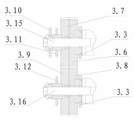
[0018] Such as figure 1 , figure 2 , image 3 with Figure 4 The shown concrete placing machine comprises a support 1 and a hopper 2 connected to the support 1, the lower end of the hopper 2 is provided with a discharge port 4, and the discharge port 4 is provided with an accelerated feeding device 3. Of course, the concrete placing machine also includes other parts, but these parts are all the same as the prior art concrete placing machine, and the invention points of the present invention are not involved, so it is not repeated here.

[0019] Described accelerated unloading device 3 comprises the motor 3.5 that is installed on the bracket 1 and the first unloading roller 3.1 that is connected in hopper 2 outlet 4 and the second unloading roller 3.2 of rotation, and described motor 3.5 is connected with the first unloading roller. A tran...


PUM


Abstract

The invention relates to a concrete spreader, comprising a bracket (1) and a hopper (2), wherein the hopper (2) is connected with the bracket (1); the lower end of the hopper (2) is provided with a discharging opening (4); and an accelerated discharging device (3) is arranged at the discharging opening (4). Compared with the prior art, the concrete spreader ensure that concrete falling from the discharging opening has certain initial speed under the action of the accelerated discharging device because the concrete spreader is provided with the accelerated discharging device, the falling speed is quicker, and the concrete is more compact when falling to a tubular pile steel die; the accelerated discharging device can also ensure that the volume of the concrete passing through the discharging opening in unit time is more than that of the concrete falling naturally in unit time, and therefore, the purpose of increasing discharging amount can be realized without increasing an aperture of the discharging opening; and because the accelerated discharging device is not in complete contact with the concrete, the viscous effect of the accelerated discharging device on the concrete is less, the power required by the accelerated discharging device is lower and the wearing is less.

Description

technical field [0001] The invention relates to a concrete distributing machine. Background technique [0002] At present, there are two types of concrete placing machines in the prior art, one is an ordinary curtain-type concrete placing machine, and the other is a dragon-type placing machine; Closing to achieve or stop the action of material distribution, the concrete in the hopper will fall by its own gravity during material distribution, if you want to increase the amount of material distribution, you need to increase the opening degree of the discharge door, but this will easily make the opening of the discharge port If the thickness is greater than the diameter of the steel formwork for pipe piles, the falling concrete is easily scattered outside the steel formwork for pipe piles and the mold closing part. It is necessary to carefully clean the steel formwork for pipe piles before closing the molds. There are problems that the blanking is not dense enough, the distrib...

Claims


Application Information

Patent Timeline
IPC IPC(8): B28B21/00B28C7/16
Inventor 张日红长谷山国广
Owner 宁波中淳高科股份有限公司
Why Eureka
Try Eureka