
Preparation method of cathode material and application of cathode material in microbial fuel cell

A cathode material, fuel cell technology, applied in battery electrodes, circuits, electrical components, etc., to achieve the effects of simple activation method, reduced construction cost, and low price

Inactive Publication Date: 2013-09-25
EAST CHINA UNIV OF SCI & TECH
View PDF4 Cites 0 Cited by
  • Summary
  • Abstract
  • Description
  • Claims
  • Application Information

AI Technical Summary

Problems solved by technology

However, the improvement of the surface oxygen reduction properties of carbon materials by chemical activation methods and the application of chemically activated carbon materials in the cathode of microbial fuel cells are rarely reported.

Method used

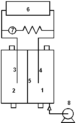

Image

  • Preparation method of cathode material and application of cathode material in microbial fuel cell
  • Preparation method of cathode material and application of cathode material in microbial fuel cell
  • Preparation method of cathode material and application of cathode material in microbial fuel cell

Examples


Embodiment 1

[0037] Step 1: Preparation and Characterization of Strong Acid-Activated Graphite Materials

[0038] (1) Clean a graphite rod with a diameter of 6 mm and 200 mL of graphite particles with a particle size of 5×4 mm with deionized water and ethanol, and air-dry. At 30°C, soak the pretreated graphite rods and graphite particles in 85% phosphoric acid for 12 hours, then rinse them with deionized water, and dry them in the air.

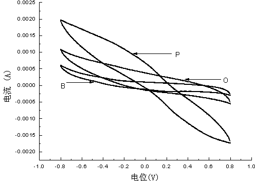
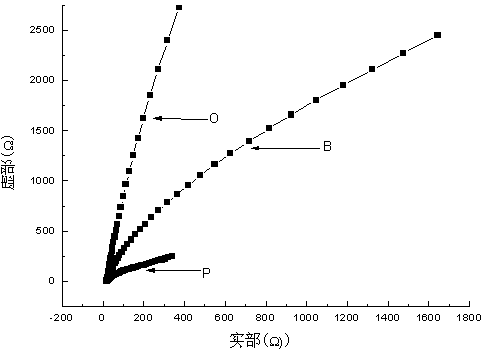
[0039] (2) Electrochemical tests were performed on graphite electrodes before and after activation: Electrochemical tests were carried out on chemically activated electrodes using a traditional three-electrode system, that is, Parstat 2273 electrochemical workstation was used at room temperature, and 50mM phosphate buffer solution (PBS ) as the electrolyte, with the calomel electrode (Hg / HgO electrode) as the reference electrode, the platinum electrode as the auxiliary electrode, and the activated electrode as the working electrode, the cyclic voltammetry ...

Embodiment 2

[0049] Step 1: Preparation and Characterization of Strong Acid Activated Graphite Materials

[0050] (1) Clean a graphite rod with a diameter of 6 mm and 200 mL of graphite particles with a particle size of 5×4 mm with deionized water and ethanol, and air-dry. At 30°C, soak graphite rods and 200mL graphite particles in 5mol / L nitric acid solution for 36h, then rinse with deionized water and dry in the air.

[0051] (2) Electrochemical tests were performed on the graphite electrodes before and after activation. The electrochemical test shows that the oxygen reduction current of the graphite electrode activated by nitric acid is significantly greater than that of the unactivated electrode in the cyclic voltammetry test, indicating that the oxygen reduction ability of the activated electrode is enhanced (see figure 2 ).

[0052] (3) Using Nicolet Fourier transform infrared spectrometer, FTIR results (see Figure 4 ) shows that the nitric acid activated graphite material is at...


PUM


Abstract

The invention discloses a preparation method of a strong acid chemically-activated cathode material and application of the cathode material in a microbial fuel cell. In the preparation method, a carbon material is soaked into strong acid such as phosphoric acid, nitric acid or sulfuric acid or the like, and the surface characteristics of the carbon material are chemically activated and modified to prepare a microbial fuel cell cathode, and the microbial fuel cell cathode is applied to the microbial fuel cell. Compared with a noble metal catalyst such as platinum and the like, the strong acid activated carbon electrode material is low in price and wide in source and greatly reduces the constructive cost of the microbial fuel cell; and compared with the electrode without strong acid activation, the strong acid activated electrode can greatly improve the oxygen reduction rate of the cathode and the electricity generation power of the cell. The application of the strong acid activated carbon cathode material remarkably reduces the constructional cost of the microbial fuel cell, and new path and possibility are provided for the application of the microbial fuel cell.

Description

technical field [0001] The invention belongs to the technical field of new energy and environmental engineering, and in particular relates to the application of chemically activated carbon materials in microbial fuel cells. Background technique [0002] Microbial Fuel Cells (MFCs) is a new type of device that uses microorganisms as catalysts to convert chemical energy in organic matter into electrical energy. It can recover electrical energy from wastewater, realizing the win-win situation of wastewater treatment and electrical energy recovery, and it has the characteristics of mild reaction conditions and no pollution. It is an ideal new energy source, which has attracted more and more attention. [0003] At present, the output power of microbial fuel cells is still very low. This is mainly due to the slow oxidation rate of the substrate by microorganisms, the small electron transfer rate, the low activation overpotential of the cathode, and the large internal resistance o...

Claims


Application Information

Patent Timeline
Patent Type & Authority Patents(China)
IPC IPC(8): H01M4/88H01M4/96
CPCY02E60/50
Inventor 张乐华李冬梅史海凤窦春玲闫莹蔡兰坤
Owner EAST CHINA UNIV OF SCI & TECH
Learn More