Power switching tube overcurrent detection and overcurrent protection circuit

An overcurrent protection circuit, power switch tube technology, applied in emergency protection circuit devices, emergency protection circuit devices, circuit devices for limiting overcurrent/overvoltage, etc., can solve problems affecting the normal operation of the system, etc. Accuracy, achieve the effect of overcurrent protection

Active Publication Date: 2011-10-05
SHANGHAI MOUNTAIN VIEW SILICON
View PDF8 Cites 42 Cited by
  • Summary
  • Abstract
  • Description
  • Claims
  • Application Information

AI Technical Summary

Problems solved by technology

However, even if the self-recovery method is added, the power MOS tube still has a state of interrupting the output. This rigid protection method will seriously affect the normal operation of some systems that require high continuity.

Method used


Image

  • Power switching tube overcurrent detection and overcurrent protection circuit
  • Power switching tube overcurrent detection and overcurrent protection circuit
  • Power switching tube overcurrent detection and overcurrent protection circuit

Examples


Embodiment 1

[0020] Embodiment 1: In this embodiment, the power switch tube is a P-type MOS tube.

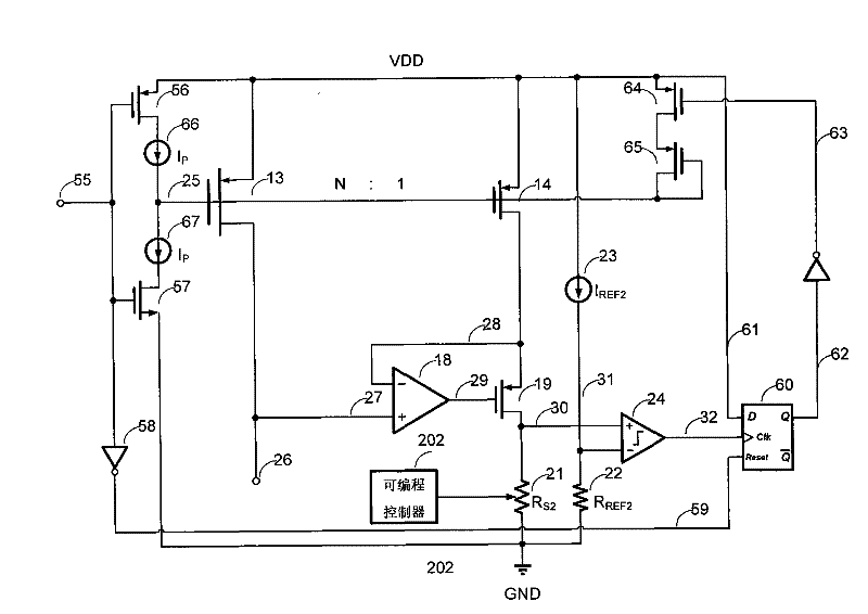
[0021] see figure 2 , The power switch tube overcurrent detection and overcurrent protection circuit of the present invention at least includes: an overcurrent detection circuit and an overcurrent protection circuit connected to the output end of the overcurrent detection circuit.

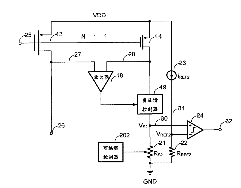
[0022] Such as image 3 As shown, it is a schematic diagram of the overcurrent detection circuit. The gate terminal 25 and the source terminal (VDD) of the sampling MOS transistor 14 are respectively connected to the gate terminal and the source terminal of the P-type power MOS transistor switch 13 . The drain terminal 27 of the power MOS transistor switch 13 and the drain terminal 28 of the sampling MOS transistor 14 are respectively connected to two input terminals of the amplifier 18 . The output terminal of the amplifier 18 is fed back to the drain terminal 28 of the sampling MOS tube 14 through the negat...

Embodiment 2

[0026] The difference between this embodiment and the first embodiment lies in that the power switch tube is an N-type MOS tube.

[0027] Such as Figure 6 As shown, the power switch tube overcurrent detection and overcurrent protection circuit includes: an overcurrent detection circuit and an overcurrent protection circuit connected to the output end of the overcurrent detection circuit.

[0028] Wherein, the overcurrent detection circuit includes: a sampling tube 35 , a negative feedback circuit, a sampling resistor 42 and a comparator 45 . The grid and the source end of the sampling tube 35 are connected with the grid and the source end of the power switch tube 34 respectively; the negative feedback circuit includes an amplifier 39 and a negative feedback controller (i.e. an N-type MOS tube) 40, and the sampling tube 35 and the power switch The drain end of the tube 34 is respectively connected to the input ends 48 and 47 of the amplifier 39, the gate end of the N-type MOS...


PUM


Abstract

The invention provides a power switching tube overcurrent detection and overcurrent protection circuit, which comprises an overcurrent detection circuit and an overcurrent protection circuit. The overcurrent detection circuit comprises a sampling tube, a negative feedback circuit, a sampling resistor and a comparator, wherein the gate and source ends of the sampling tube are connected with the gate and source ends of a power switching tube to be detected; the negative feedback circuit can make the drain voltage of the sampling tube tend to be consistent with the drain voltage of the power switching tube; the sampling resistor is used for introducing current flowing through the sampling tube; and the comparator compares the voltage or current of the sampling resistor with an overcurrent reference voltage or current to judge whether the power switching tube has overcurrent or not to realize high-accuracy overcurrent detection. The overcurrent protection circuit comprises a latch used for receiving and latching a detected overcurrent signal, a power switching tube driving circuit and a mirror current tube circuit with a switch. When the switch is switched off, the mirror current tube circuit samples the current of the power switching tube driving circuit, and mirrors the sampled current into the current of the power switching tube to realize the overcurrent protection of the power switching tube.

Description

technical field [0001] The invention relates to a power switch tube overcurrent detection and overcurrent protection circuit. Background technique [0002] Switching amplifiers, switching power supplies, and charge pumps use the turn-on and turn-off of power MOS tube switches to achieve high-efficiency conversion of signals and energy, and have more and more applications. Such a power MOS tube switch usually has a large current flowing when it is turned on, and if the current exceeds the withstand limit of the power MOS tube switch, the power MOS tube switch may be permanently damaged. Therefore, in order to ensure the reliability of the device, the current flowing through the power MOS tube switch must be continuously detected, and the power MOS tube switch can be protected when the current is too large. [0003] Regarding the detection of the current flowing through the power MOS tube switch, the most widely used method is as follows: figure 1 As shown, its core idea is ...

Claims


Application Information

Patent Timeline
Patent Type & Authority Applications(China)
IPC IPC(8): H02H9/02G01R19/165
Inventor 程晋
Owner SHANGHAI MOUNTAIN VIEW SILICON
Why Eureka
Try Eureka