Heating wire for lighter

A technology of electric heating wire and lighter, which is applied in the direction of ohmic resistance heating parts, combustion ignition, heating elements, etc., which can solve the problems that cannot guarantee fast ignition and achieve the effect of convenient connection

Inactive Publication Date: 2011-10-05
刘广
View PDF0 Cites 1 Cited by
  • Summary
  • Abstract
  • Description
  • Claims
  • Application Information

AI Technical Summary

Problems solved by technology

[0003] It can be seen that although electric lighters use electric heat to ignite cigarettes, they cannot guarantee that they can be ignited as quickly as cotton lighters, gas lighters, and matches, and are reliable in use.

Method used


Image

  • Heating wire for lighter
  • Heating wire for lighter

Examples


Embodiment Construction

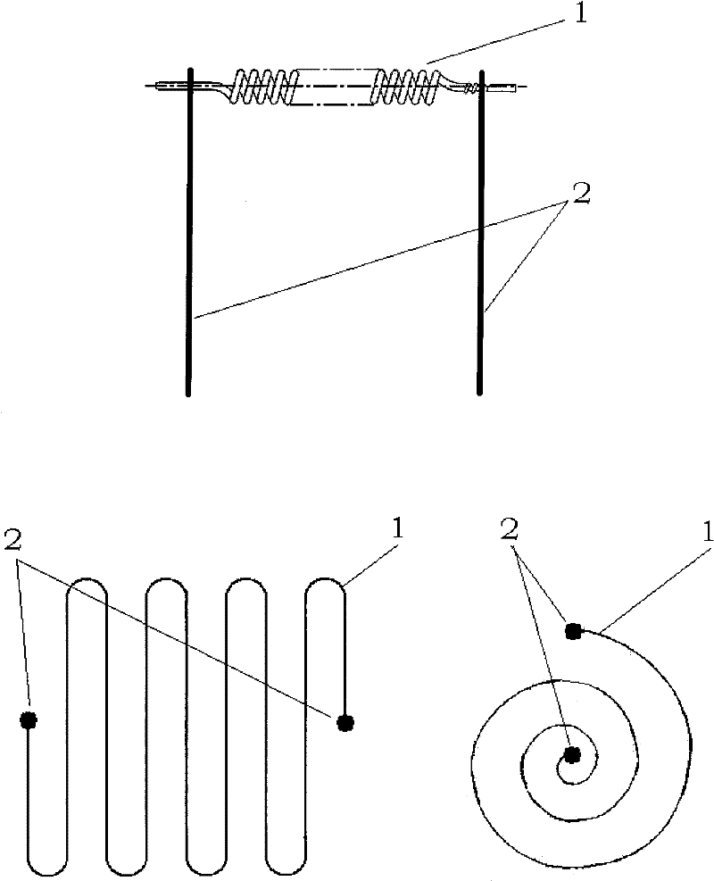
[0014] refer to figure 1 According to the cold resistance of 1.7-45Ω, the electric heating wire 1 is wound into a spiral structure to make a linear or planar shape, or made of a flat electric heating wire. The best cold resistance is 6-13Ω, and the two ends are respectively connected to two metal One end of the rod 2 is made into an integral puller by welding or cold pressing.

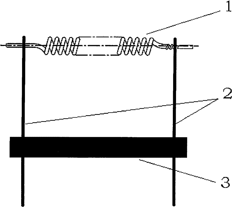
[0015] figure 2 The two metal rods 2 shown can also be made to be placed separately in parallel, and an "H" shape fixed by an insulator 3 is horizontally placed in the middle, and then a pull-out plug-in unit fixed with the two ends of the heating wire 1 as one.

[0016] The metal rod 2 is fixed with the heating wire 1 and is plugged and connected with the lighter so that the heating wire 1 is connected to the circuit, which is convenient for use and maintenance.


PUM


Abstract

The invention relates to a heating wire for a lighter. Two metal bars are fixed with the heating wire into a whole, and are connected with the lighter in a plugging mode so as to insert the heating wire into a circuit. The heating wire is electrified and heated to the temperature of 400 to 450 DEG C, so a cigarette can be easily ignited; moreover, no combustion or waste is generated during ignition; the manufacturing process is environment-friendly, the heating wire has low cost and long service life and is convenient to maintain and use.

Description

technical field [0001] The invention relates to an electric heating lighter, in particular to an electric heating wire for a lighter with a built-in generator. Background technique [0002] Known electrothermal lighter is to ignite cigarette in the mode of electrothermal. However, in the above-mentioned electric lighter, the configuration relationship of the electric heating wire components and the connection mode between the electric heating wire and the lighter are not specified. [0003] It can be seen that although electric lighters use electric heat to ignite cigarettes, they cannot guarantee that they can be ignited quickly and reliably like cotton lighters, gas lighters, and matches. Contents of the invention [0004] The object of the present invention is to provide an environmentally safe, reliable, convenient and economical heating wire for lighters. [0005] In order to achieve the above object, the present invention provides a heating wire for a lighter. The ...

Claims


Application Information

Patent Timeline
Patent Type & Authority Applications(China)
IPC IPC(8): H05B3/06F23Q7/22
Inventor 刘思吕晶刘广
Owner 刘广
Why Eureka
Try Eureka