Column-beam connection structure

A technology for joints and columns and beams, applied in welding equipment, building structures, welding/welding/cutting items, etc., can solve the problems that the beam web cannot be expected to bear, and achieve increased plate thickness, prevention of embrittlement, and bending moment bearing big effect

Inactive Publication Date: 2011-10-05
ARCREATE
View PDF1 Cites 6 Cited by
  • Summary
  • Abstract
  • Description
  • Claims
  • Application Information

AI Technical Summary

Problems solved by technology

However, as far as the bending moment is concerned with the beam, the plate 2 unde...

Method used


Image

  • Column-beam connection structure
  • Column-beam connection structure
  • Column-beam connection structure

Examples


Embodiment Construction

[0043] Embodiments of the present invention will be described below.

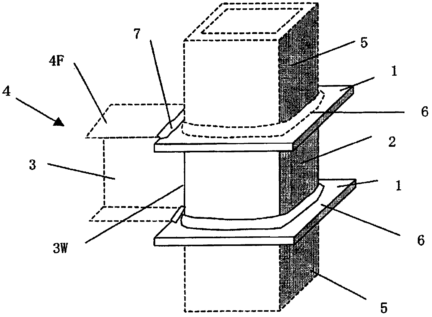
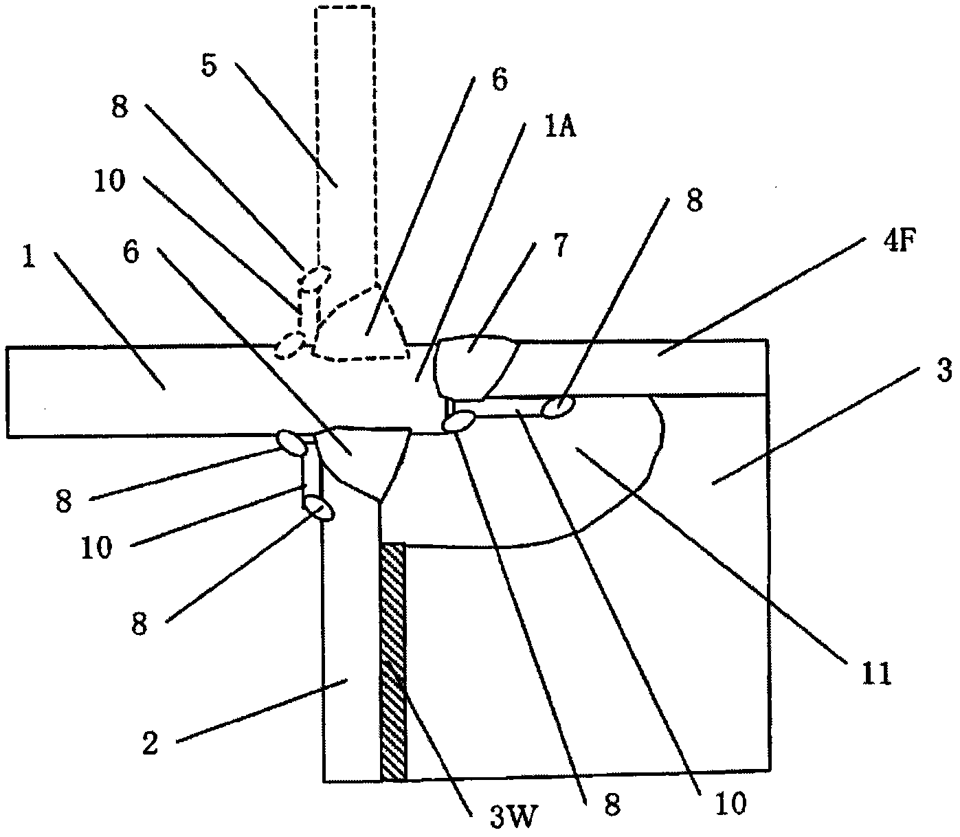
[0044] As an example of the embodiment of the present invention described in claim 1, Figure 5 It shows an example of removing the protrusion of the partition plate 1 from the column 5 in the column-beam junction of the building steel frame, increasing the thickness 1t of the partition plate 1, and connecting the column shaft 5 and the welded part 7 of the partition plate 1 and the beam flange 4F It overlaps and joins with the welded part 7 of the separator 1, and welds at least the thickened part of the separator 1 that increases by 5 mm or more, preferably 35 mm or more, to the web of the beam. In the case of increasing the thickness of the partition to 1 / 2 of the height of the web, it is possible to use a structure that integrates the upper and lower partitions, or weld the middle of the two partitions to omit the middle column short tube .

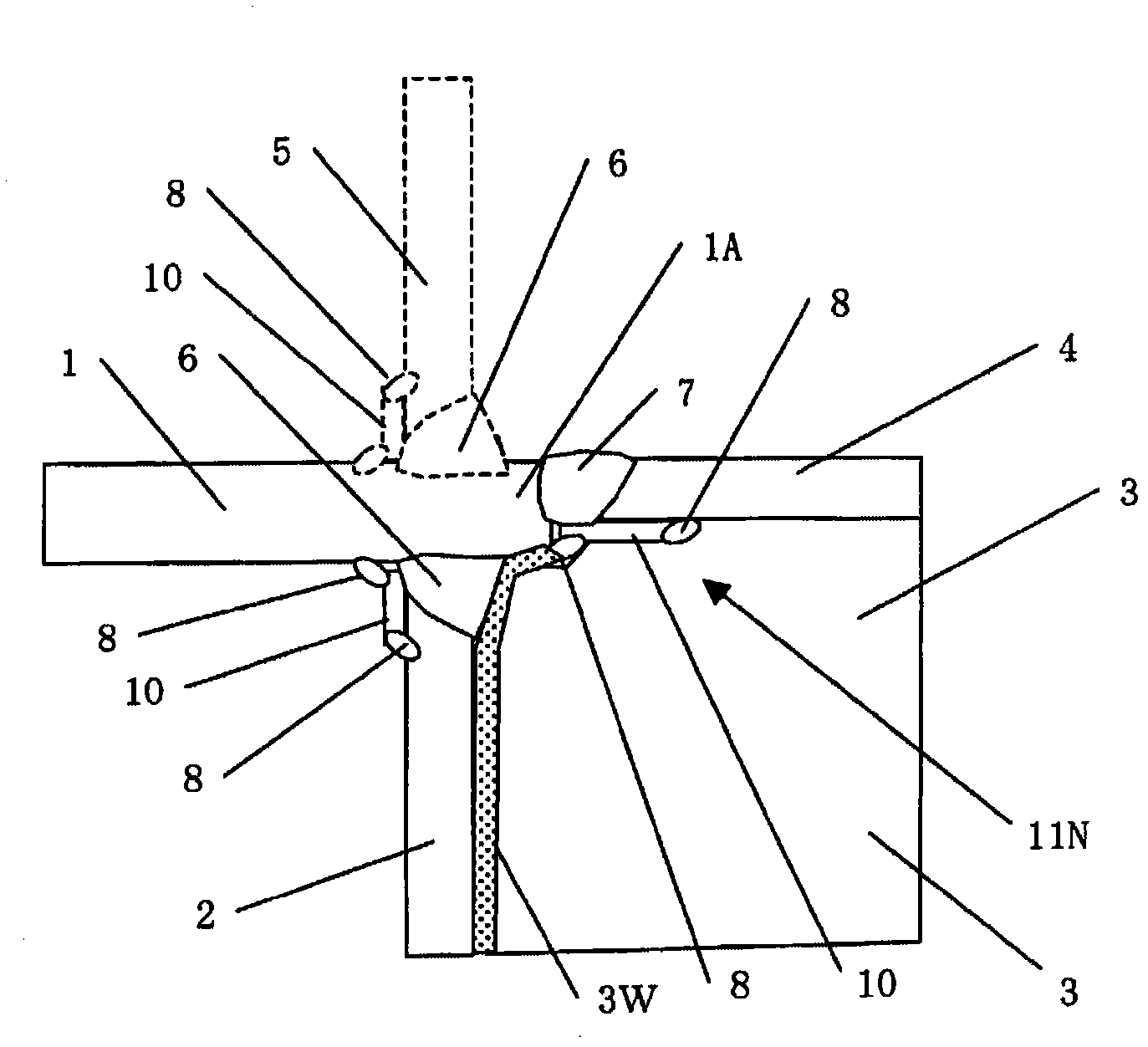
[0045] Such as Figure 6 As shown, as an example of the em...


PUM


Abstract

Bending moment applied to a beam causes out-of-plane deformation to a panel when the panel zone is hollow, and thereby a load bearing by a web cannot be expected in an elastic region. Since the section modulus of a beam end which is used in the structure calculation of a building structure is limited to the section modulus of only the flange not including the web, the beam end has a low strength. Therefore, a beam larger in size must be used and an extra beam depth is required, thus causing an increase in the weight of a steel beam. As the result of various studies, it has been found that various problems could be resolved by significantly increasing the plate thickness of a diaphragm in the direction of the web, and imparting prestress by hot working or overlaying the underside surface of the beam.

Description

technical field [0001] The invention relates to a column-beam joint structure of a steel frame structure. Background technique [0002] As far as the structure of the building steel frame structure is concerned, in the case of using a through partition form of a column with a rectangular section or a column with a circular section, such as figure 1 As shown, it consists of a column 5, a beam 4, a plate 2, and a partition 1 passing through the column 5 and the plate 2. The beam flange 4F is welded 7 to the partition 1 protruding from the column 5, and the beam web 3 is welded 3W to the plate 2. superior. There is also a form of this separator that uses an inner separator that does not pass through the column but is inserted into the column. In this case, both the beam flange 4F and the web 3 are welded to the plate 2 . Such as figure 2 As shown, the cross-section of the column-beam junction in the case of a through-wall form is generally provided with an arc-shaped notch...

Claims


Application Information

Patent Timeline
IPC IPC(8): B23K9/00E04B1/24B23K9/04
CPCE04B1/2403B23K31/02E04B2001/2454E04B2001/2415E04B2001/2445B23K2201/24E04B2001/2448B23K2101/24
Inventor 内田昌克岩乡俊二岩乡速雄
Owner ARCREATE
Why Eureka
Try Eureka