Supercharge Your Innovation With Domain-Expert AI Agents!

Multi-channel receiver architecture and reception method

A receiver, multi-channel technology, applied in the direction of TV, color TV, transmission system, etc., can solve the problem of high complexity

Active Publication Date: 2011-10-05
NXP BV
View PDF5 Cites 9 Cited by
  • Summary
  • Abstract
  • Description
  • Claims
  • Application Information

AI Technical Summary

Problems solved by technology

The second major issue is the ability to handle digital signals with very high data rates
In both cases the complexity is significantly higher as the circuits that must be synchronized may be separated by 1-10cm

Method used


Image

  • Multi-channel receiver architecture and reception method
  • Multi-channel receiver architecture and reception method
  • Multi-channel receiver architecture and reception method

Examples


Embodiment Construction

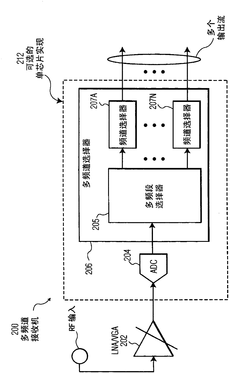
[0042] In an embodiment, the multi-channel receiver uses an analog-to-digital converter (ADC) and a high-speed multi-band selector (MBS) to provide multi-channel output to external devices. In another embodiment, ADC and MBS are implemented on a single IC. In this embodiment, data travels very small distances across the chip in a synchronous manner. IC receivers output only pre-selected channel information at a significantly lower data rate (eg, 10M samples / s instead of 2G samples / s), mitigating Electromagnetic Compatibility (EMC) issues. figure 2 Logical components of a multi-channel receiver (MCR) according to an embodiment are illustrated.

[0043] MCR 200 includes LNA / VGA 202 , ADC 204 and multi-channel selector 206 . Multi-channel selector 206 includes multi-band selector 205 and channel selectors 207A-207N. Depending on the number of tuners implemented in the multi-channel selector 206, the number of output streams that will be available will be determined. In an emb...


PUM


Abstract

A multi-channel receiver comprising an ADC and a multi-band, multi-channel selector. The ADC converts a broad-band multi-channel signal into a digital signal. The digital signal is then broken into sub-bands each containing a plurality of channels. A channel selector selects desired channels from the appropriate sub-band. The multi-channel receiver may deliver simultaneous channels equal to the number of channel selectors that have been implemented. The multi-channel receiver may be implemented on a single integrated circuit.

Description

Background technique [0001] Current television receivers receive a single channel through a single tuner. The growing market for data and program services will require receivers with multi-channel tuning capabilities. [0002] A block diagram of a conventional single channel cable television receiver is illustrated in FIG. The composite TV signal is received at the input of the receiver and amplified to the correct level using a low noise amplifier and variable gain amplifier (LNA / VGA) 102 . The programmable band selection filter 104 can potentially pre-select the composite signal to limit its bandwidth and facilitate subsequent signal processing operations. [0003] A particular TV channel is selected using the frequency synthesizer 106, which is tuned to the corresponding channel frequency. By multiplying together the synthesized frequency reference signal and the received signal with the help of mixer circuit 108, the desired channel is down-converted (offset from its ca...

Claims


Application Information

Patent Timeline
Patent Type & Authority Applications(China)
IPC IPC(8): H04N5/44H04N21/2365H04N21/434
CPCH03H17/06H03H2218/08H04B1/0025H04B1/001
Inventor 康斯坦丁诺斯·多丽丝埃尔温·杨森
Owner NXP BV
Features
  • R&D
  • Intellectual Property
  • Life Sciences
  • Materials
  • Tech Scout
  • Unparalleled Data Quality
  • Higher Quality Content
  • 60% Fewer Hallucinations
Learn More