Automatic blowing mechanism on mold

A blowing mechanism and automatic technology, applied in the field of automatic blowing mechanism and product blowing mechanism, can solve the problem that ordinary molds cannot be formed, and achieve the effect of simple structure and easy operation.

Inactive Publication Date: 2011-10-12
WUXI GISSING AUTO ACOUSTIC PARTS TECH CO LTD
View PDF3 Cites 8 Cited by
  • Summary
  • Abstract
  • Description
  • Claims
  • Application Information

AI Technical Summary

Problems solved by technology

[0003] The purpose of the present invention is to overcome the deficiencies in the prior art, provide a simple, compact, reasonable and easy-to-operate automatic blowing mechanism on the mold, and overcome the situation that ordinary molds cannot be formed when products need to be blown into shape

Method used


Image

  • Automatic blowing mechanism on mold
  • Automatic blowing mechanism on mold
  • Automatic blowing mechanism on mold

Examples


Embodiment Construction

[0013] The present invention will be further described below in conjunction with specific drawings.

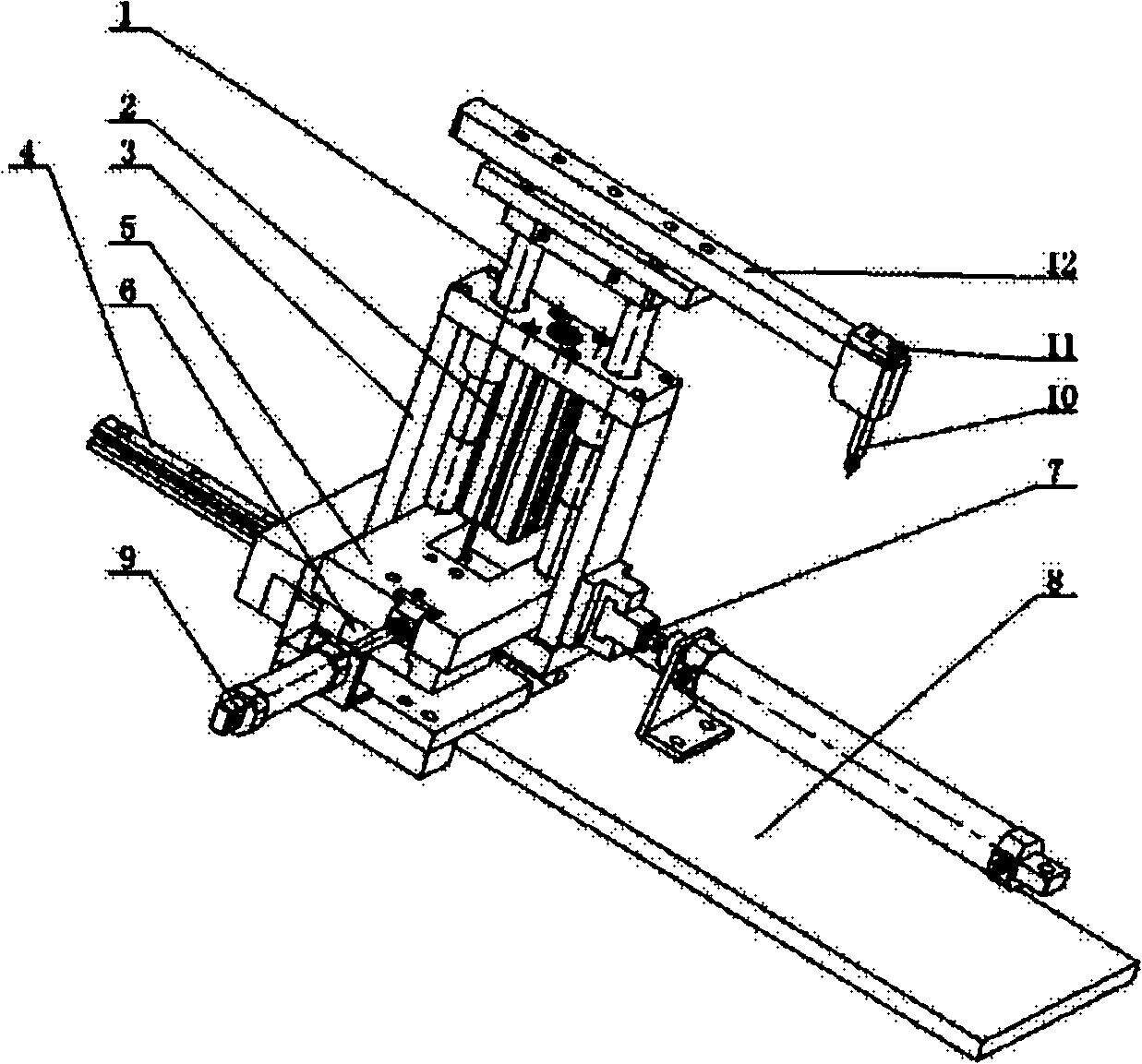
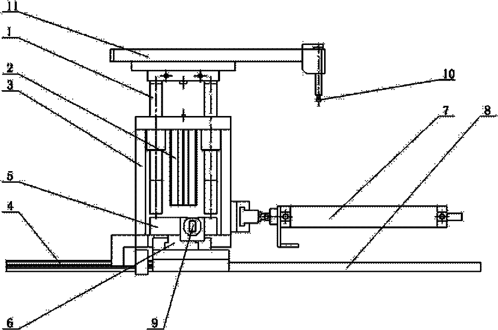
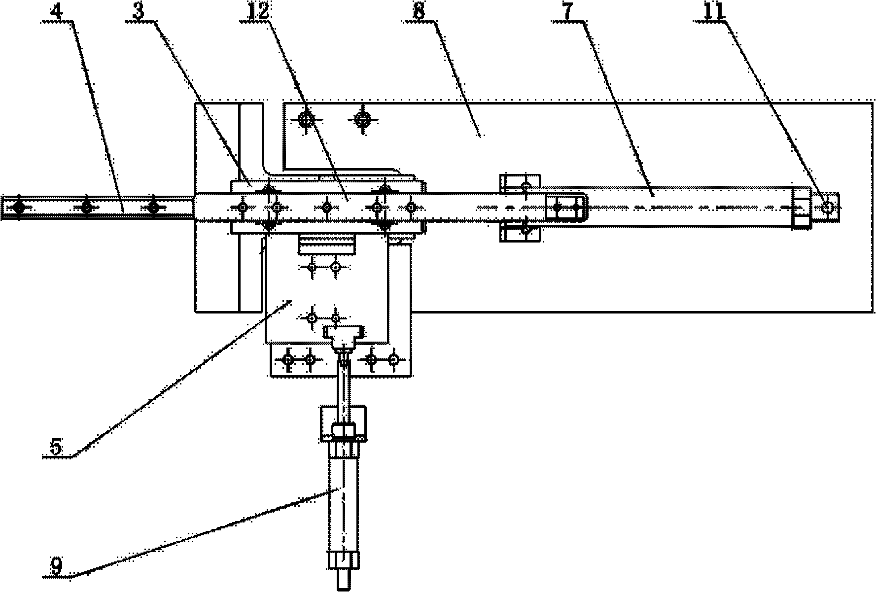
[0014] like Figure 1 to Figure 4 Shown: The automatic blowing mechanism on the mold includes guide rail 1, first cylinder 2, support frame 3, first guide rail 4, height limit block 5, second guide rail 6, second cylinder 7, lateral limit block 8. The third air cylinder 9, air blowing needle 10, trachea joint 11, air needle fixing rod 12, etc.

[0015] The present invention includes a support frame 3, a hole and a first cylinder 2 are arranged above the support frame 3, and a guide rod 1 is arranged in the hole, and the guide rod 1 can be driven by the piston rod of the first cylinder 2 Slide up and down in the hole; an air needle fixing rod 12 is erected above the guide slide rod 1, and one end of the air needle fixing rod 12 is provided with an air blowing needle 10, and the air blowing needle 10 is connected with the trachea joint 11;

[0016] A first guide rail 4 is arra...


PUM


Abstract

The invention relates to an automatic blowing mechanism on a mold. The mechanism comprises a supporting frame, and is characterized in that: a hole and a first cylinder are arranged above the supporting frame; a guide sliding rod is arranged in the hole, and can slide up and down in the hole under the driving action of the first cylinder; a gas needle fixing rod is erected above the guide sliding rod; a blowing needle is arranged at one end of the gas needle fixing rod; a first guide rail is arranged below the supporting frame; a transverse limiting block is arranged on one side of the supporting frame; a second cylinder is arranged on the transverse limiting block; the supporting frame can slide on the first guide rail under the driving action of the second cylinder; and a height limiting block is arranged below the supporting frame, is arranged on the second guide rail, is connected with a piston rod of a third cylinder and can slide on the second guide rail under the driving action of the third cylinder. The mechanism has a simple, compact and reasonable structure, is easy to operate, and can meet the requirement of the production process of a special automobile interior trim part product on the basis of not changing the structure of the mold.

Description

technical field [0001] The invention relates to an automatic blowing mechanism on a mold, in particular to a mechanism for blowing air on a mold used to produce automotive interior products, and belongs to the technical field of molds. Background technique [0002] At present, in the production of coat racks for automotive interior parts, some coat racks need to be blown into shape, and ordinary molds for such coat racks cannot be formed, so an automatic blowing mechanism needs to be added to the mold. Existing molds generally do not have a blowing mechanism, and for those products that require blow molding, ordinary molds cannot be formed. Contents of the invention [0003] The purpose of the present invention is to overcome the deficiencies in the prior art, provide a simple, compact, reasonable and easy-to-operate automatic blowing mechanism on the mold, and overcome the situation that ordinary molds cannot be formed when products need to be blown into shape [0004] A...

Claims


Application Information

Patent Timeline
Patent Type & Authority Applications(China)
IPC IPC(8): B29C49/58
Inventor 苏晓鑫
Owner WUXI GISSING AUTO ACOUSTIC PARTS TECH CO LTD
Why Eureka
Try Eureka