Ultrasonic aluminum foil welding machine

A welding machine and ultrasonic technology, applied in welding equipment, non-electric welding equipment, metal processing equipment, etc., can solve problems affecting the quality of lithium batteries, achieve the effect of meeting the production process and improving quality

Inactive Publication Date: 2018-03-16
ZHAOQING HI TECH ZONE GUOZHUAN TECH CO LTD
View PDF7 Cites 1 Cited by
  • Summary
  • Abstract
  • Description
  • Claims
  • Application Information

AI Technical Summary

Problems solved by technology

At present, there is no ultrasonic equipment specially used for welding the end face of aluminum foil o

Method used


Image

  • Ultrasonic aluminum foil welding machine
  • Ultrasonic aluminum foil welding machine
  • Ultrasonic aluminum foil welding machine

Examples


Embodiment approach

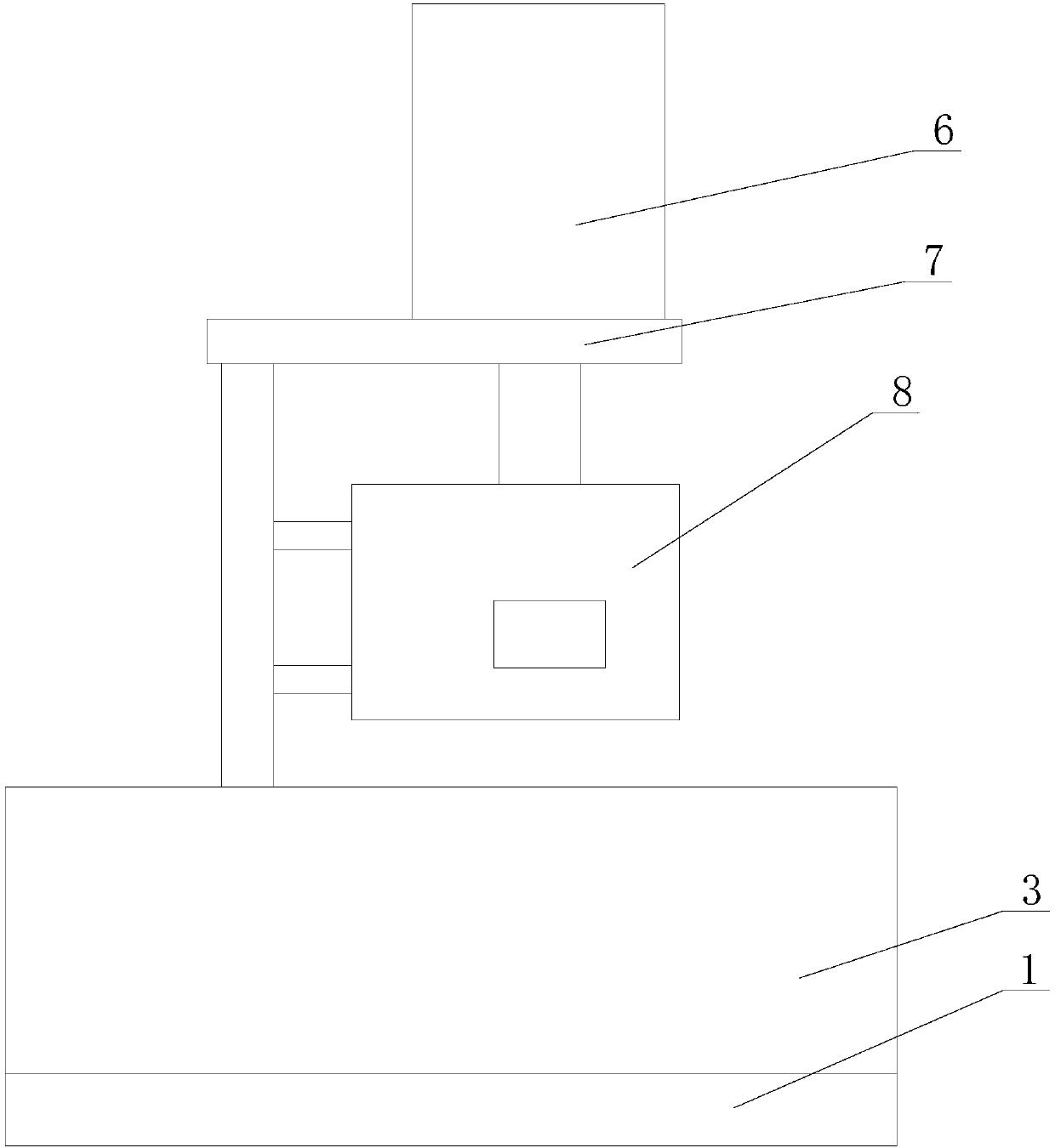
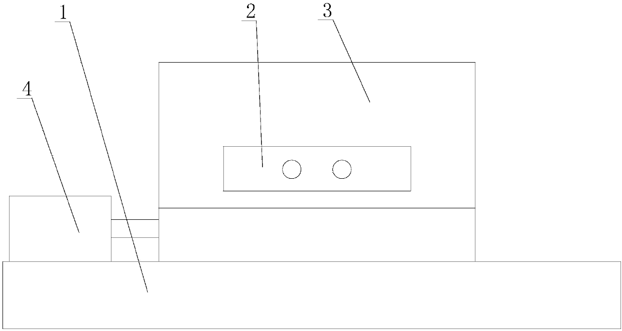
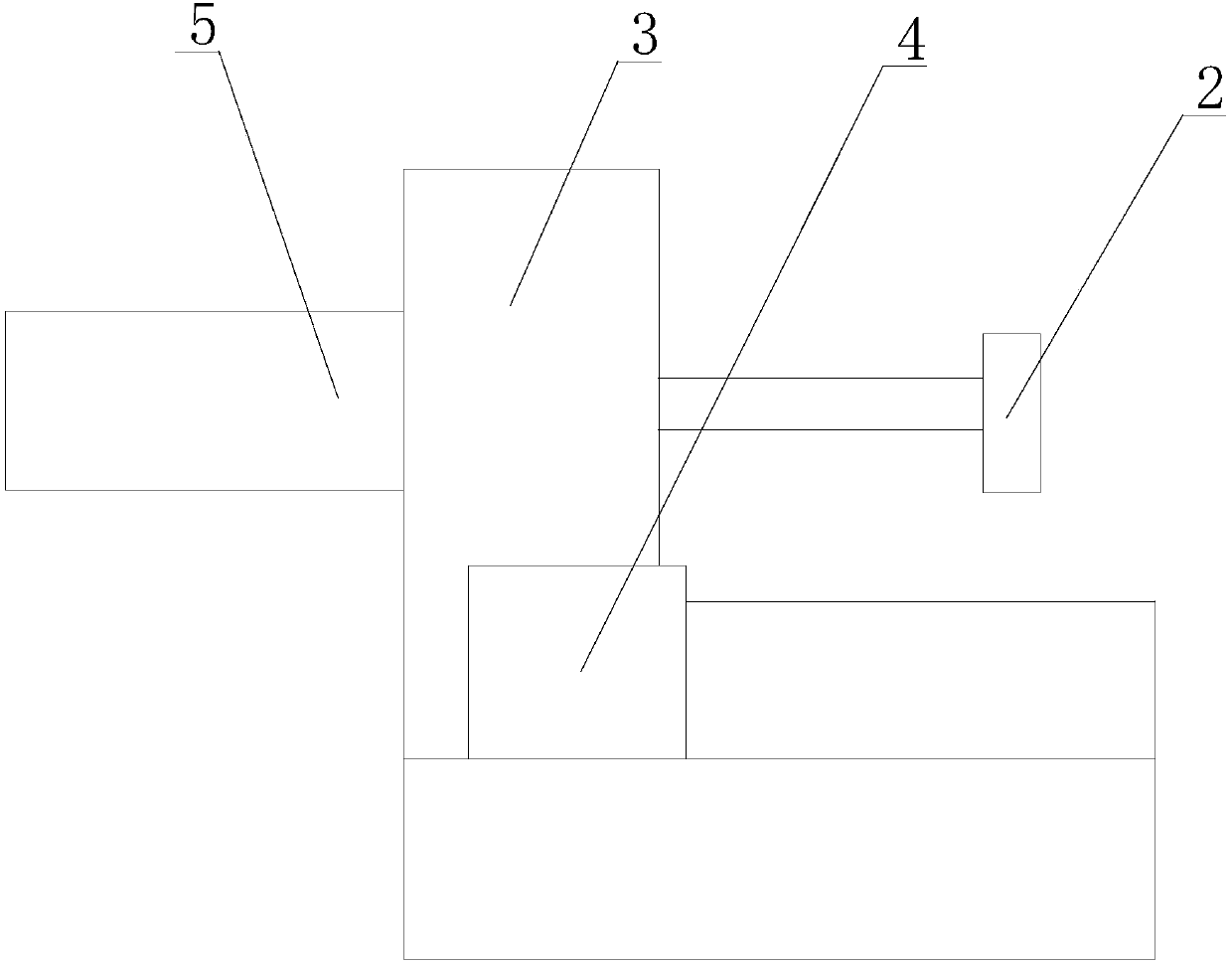
[0019] figure 1 , figure 2 and image 3 An embodiment of the ultrasonic aluminum foil welding machine of the present invention is shown, including a welding head assembly, a base 1 and a clamping assembly, the welding head assembly and the clamping assembly are installed on the base 1, and the welding assembly moves up and down relative to the base 1, The clamping assembly includes a clamping plate 2 , a mounting base 3 and a driving assembly. The clamping plate 2 clamps or loosens the aluminum foil through the driving assembly and the mounting base 3 .

[0020] In this embodiment, the drive assembly includes a first drive motor 5 and a second drive motor 4, the mount 3 is fixed on the base 1, the first drive motor 5 is fixed on the mount 3, and the drive shaft of the first drive motor 5 passes through The mounting base 3 is fixedly connected with the clamping plate 2, the second driving motor 4 is fixed on the base 1, the drive shaft of the second driving motor 4 is fixedl...


PUM


Abstract

The invention discloses an ultrasonic aluminum foil welding machine. The ultrasonic aluminum foil welding machine comprises a welding head assembly, a base and a clamping assembly. The welding head and the clamping assembly are mounted on the base; the welding head assembly lifts relative to the base; the clamping assembly comprises a clamping plate, a mounting seat and a driving assembly; and theclamping plate clamps an aluminum foil or loosens the aluminum foil through the driving assembly and the mounting seat. The ultrasonic aluminum foil welding machine disclosed by the invention has theadvantages of being simple in structure, convenient to operate and wide in application range.

Description

technical field [0001] The invention belongs to the technical field of ultrasonic welding, and more specifically relates to an ultrasonic aluminum foil welding machine. Background technique [0002] Ultrasonic welding is a method that uses high-frequency vibration waves to transmit to the surfaces of two objects to be welded. Under pressure, the surfaces of the two objects are rubbed against each other to form a fusion method between molecular layers. The ultrasonic welding machine converts 50 / 60 Hz current into 15, 20, 30 or 40KHz electric energy through the ultrasonic generator during operation. The converted high-frequency electric energy is converted again into mechanical motion of the same frequency through the transducer, and then the mechanical motion is transmitted to the welding head through the horn device on the transducer. The welding head transmits the received vibration energy to the joint of the workpiece to be welded. In this area, the vibration energy is co...

Claims


Application Information

Patent Timeline
IPC IPC(8): B23K20/10B23K20/26
Inventor 林静霞林心品
Owner ZHAOQING HI TECH ZONE GUOZHUAN TECH CO LTD
Why Eureka
Try Eureka