Auxiliary handle

An auxiliary handle and wrench technology, applied in the field of auxiliary handles, can solve the problems of whitening, breakage, unfavorable cost control and process requirements, etc., and achieve the effect of being favorable for cost control and satisfying the manufacturing process.

Inactive Publication Date: 2016-10-26
SKYBEST ELECTRIC APPLIANCE SUZHOU CO LTD
View PDF13 Cites 1 Cited by
  • Summary
  • Abstract
  • Description
  • Claims
  • Application Information

AI Technical Summary

Problems solved by technology

[0008] However, during the clamping process of the clamping part 44, since there is no limit structure on the shank of the bolt 50, this will result in the process of locking the clamping part 44 of the auxiliary handle. The first clamping arm 444 is too close to the second clamping arm 446, so that the plastic structure of the first clamping arm and the second clamping arm will be partially whitened and broken due to excessive deformation. The joint between the first clamping arm 444 , the second clamping arm 446 and the sleeve rod hole 442
Therefore, in order to overcome this defect, it is necessary to ensure the strength of the corresponding local structure of the clamp arm, so that the local structure of the clamp arm of the auxiliary handle is designed to be very thick, which is not conducive to cost control and process requirements.

Method used


Image

  • Auxiliary handle
  • Auxiliary handle
  • Auxiliary handle

Examples


Embodiment Construction

[0043] The following is a further non-limiting detailed description of the technical solution of an auxiliary handle involved in the present invention in combination with preferred embodiments and accompanying drawings.

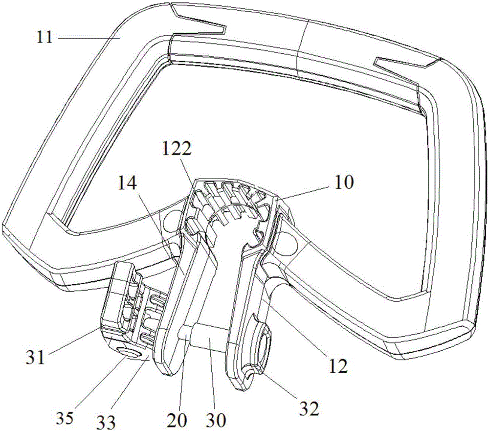
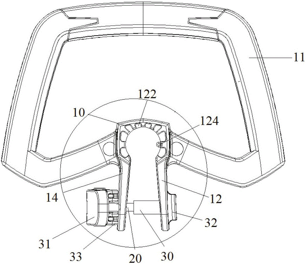
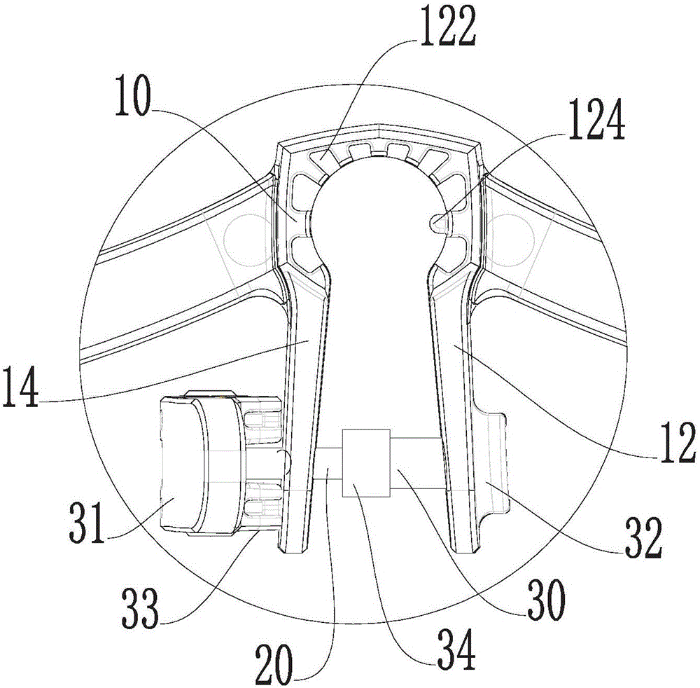
[0044] see figure 1 , 2 As shown in and 3, an embodiment of the present invention provides an auxiliary handle, which includes a sleeve rod portion 10 with an opening, a grip portion 11 and a clamping portion. The clamping portion includes a first clamping arm 12 and a second clamping arm 14 connected to both ends of the opening of the sleeve rod portion 10 . A buffer groove 122 and a positioning protrusion 124 are disposed on the inner wall of the shaft portion 10 .

[0045] Further, the first clamping arm 12 and the second clamping arm 14 are also provided with a clamping limiting device, which includes a connecting rod 20 and a clamp between the first clamping arm 12 and the second clamping arm 14 The limiting member 30, in one embodiment, the limiting...


PUM


Abstract

The invention discloses an auxiliary handle which comprises a loop bar part (10) provided with an opening, and a clamping part. The clamping part comprises a first clamping arm (12) and a second clamping arm (14) which are connected with the two ends of the opening of the loop bar part (10). A limiting part (30) is arranged between the first clamping arm (12) and the second clamping arm (14). The minimum distance, between the first clamping part (12) and the second clamping arm (14), at the position of the limiting part (30) is limited by the limiting part (30). By means of the auxiliary handle, the problems that the clamping arms are locally whitened and fractured due to deformation generated by excessive clamping and approaching can be effectively solved.

Description

technical field [0001] The invention relates to an auxiliary handle which can be used on garden tools. Background technique [0002] With the development of society and the continuous improvement of people's living standards, garden tools are no longer tools used by professionals, and the general public will also use garden tools in their daily lives. [0003] Take pruning shears and mowers among garden tools as examples. In the past, this kind of garden tools were used by specialized garden workers. But in recent years, it has also begun to be contacted by the general public, for example, it is used for pruning branches and leaves and leveling green spaces in the community environment. [0004] Garden tools, such as hand-held lawn trimmers, brush cutters, chain saws, etc., are heavy and long in shape, and are operated by a single main handle, and users generally find it laborious to use. Therefore, an auxiliary gripping part, that is, an auxiliary handle structure, is usu...

Claims


Application Information

Patent Timeline
Patent Type & Authority Applications(China)
IPC IPC(8): B25F5/02B25G3/26
CPCB25F5/02B25G3/26
Inventor 孔钊魏娟张添荣
Owner SKYBEST ELECTRIC APPLIANCE SUZHOU CO LTD
Why Eureka
Try Eureka