Dual jet system

A dual-nozzle and nozzle-pump technology, applied in the charging system, jet pump, engine components, etc., can solve problems such as smooth filling, and achieve the effect of improving fuel supply efficiency

Inactive Publication Date: 2011-10-12
COAVIS
View PDF6 Cites 2 Cited by
  • Summary
  • Abstract
  • Description
  • Claims
  • Application Information

AI Technical Summary

Problems solved by technology

[0019] In order to solve the above technical problems, the present invention provides a fuel pump module, which can prevent the fuel tank from being tilted to one side due to the tilt of the fuel tank, which cannot be poured smoothly through the hole of the nozzle pump when the vehicle is running on a steep slope area. Phenomena in memory

Method used


Image

  • Dual jet system
  • Dual jet system
  • Dual jet system

Examples


Embodiment Construction

[0059] Next, the fuel pump module 1000 of the present invention having the above-mentioned features will be described in detail with reference to the accompanying drawings.

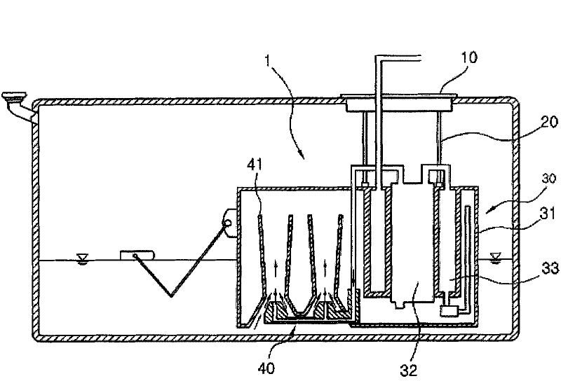
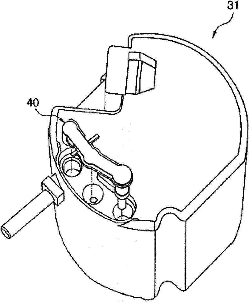
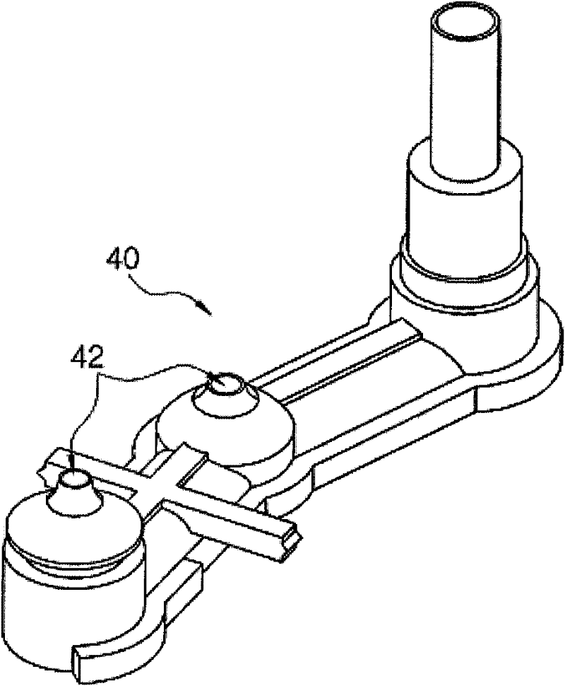
[0060] figure 1 is a schematic cross-sectional view of an existing fuel pump module; figure 2 It is a three-dimensional schematic diagram of the memory of the existing fuel pump module and the nozzle pump; image 3 It is a three-dimensional schematic diagram of a nozzle pump of an existing fuel pump module; Figure 4 It is a schematic cross-sectional view of the fuel pump module of the present invention; Figure 5 It is a three-dimensional schematic diagram of the memory of the fuel pump module and the dual-nozzle system of the present invention; Image 6 It is a schematic cross-sectional view of the inclined state of the fuel pump module of the present invention; Figure 7 It is a three-dimensional schematic diagram of the main nozzle pump of the fuel pump module of the present invention; Figure 8...


PUM


Abstract

Provided is a dual jet system mounted at a bottom end of a reservoir in a fuel pump module, and more particularly, to a fuel pump module mounted with a dual jet system capable of preventing a phenomenon that fuel is not smoothly filled in a reservoir due to fuel inclined to one side caused by an inclination of a fuel tank when a vehicle travels a steep slope section by mounting two jet pumps at both edges of a bottom end of a reservoir.

Description

technical field [0001] The present invention relates to a dual-nozzle system arranged on the lower end of the accumulator of a fuel pump module, and in more detail, relates to a fuel pump module equipped with a dual-nozzle system, which is provided with two nozzle pumps at the edge positions on both sides of the lower end of the accumulator , when the vehicle is running in a steep slope area, it can prevent the fuel from tilting to one side due to the tilt of the fuel tank, which will cause the fuel to be unable to be smoothly poured into the storage tank. Background technique [0002] Generally speaking, the fuel supply device of the vehicle supplies the required fuel to the fuel device of the vehicle, such as a gasoline engine or a diesel engine, which is driven by liquid fuel supply, so that the engine can achieve the best combustion state under any operating conditions. , plays an important role in affecting the output power or thermal efficiency of the vehicle. [0003...

Claims


Application Information

Patent Timeline
Patent Type & Authority Applications(China)
IPC IPC(8): F02M37/18
CPCF02M37/025F02M37/106F02M37/18F04F5/10
Inventor 金庆焕金正植金会显
Owner COAVIS
Why Eureka
Try Eureka