Dust collection device for vibration bed mixed flow dryer

A technology of dust removal device and dryer, which is applied in the direction of drying solid materials, drying, lighting and heating equipment, etc. It can solve the problems of restricting the hot air passing capacity of the dryer, excessive dust in the workplace, and poor air outlet of the dryer. Achieve the effect of low total investment and operation and maintenance costs, convenient maintenance and management, and guaranteed drying capacity

Active Publication Date: 2014-04-30
CHINA SHENHUA ENERGY CO LTD
View PDF8 Cites 0 Cited by
  • Summary
  • Abstract
  • Description
  • Claims
  • Application Information

AI Technical Summary

Problems solved by technology

Seriously restrict the hot air passing capacity of the dryer and the ventilation cost is high, the drying capacity is only about 50% of the design capacity; the equipment has poor reliability, low efficiency and high comprehensive cost
[0009] 2. Due to the large resistance of the bag filter during normal operation and it is located in the middle of the outlet air duct of the dryer, the air flow outlet of the dryer is seriously blocked, so that the internal air pressure of the dryer is higher than the atmospheric pressure when the dryer is running.
Because there are coal flow openings on the upper and lower sides of the dryer and the joints of the dryer itself cannot be tight and airtight, the dusty gas in the dryer leaks out under the action of the difference in internal and external air pressure, resulting in serious dust in the workplace, and , making it extremely difficult to control coal dust in the working environment

Method used


Image

  • Dust collection device for vibration bed mixed flow dryer
  • Dust collection device for vibration bed mixed flow dryer
  • Dust collection device for vibration bed mixed flow dryer

Examples


Embodiment Construction

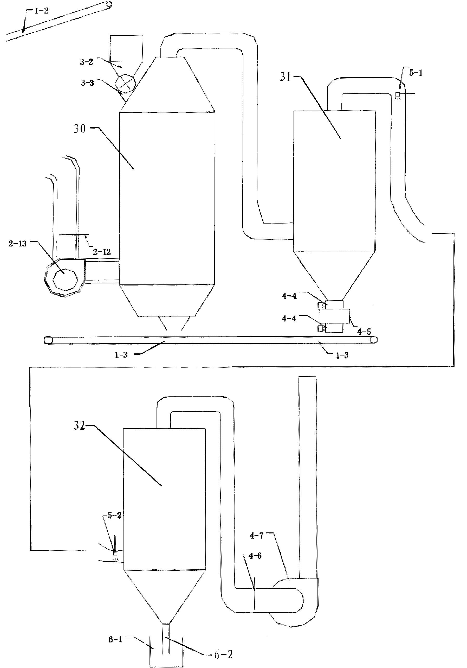
[0030] see image 3 , which shows a preferred embodiment of the dust removal device of a vibrating bed mixed-flow dryer of the present invention, including a dryer 30 and at least one cyclone dust removal chamber 31 and a secondary cyclone dust removal chamber connected in sequence with the dryer 30 through pipelines 32. A steam humidifier 5-1 is provided in the outlet pipe at the top of the primary cyclone chamber 31, and a sprayer 5-2 is provided at the entrance of the secondary cyclone chamber 32. The steam humidifier 5-1 of the present invention and the sprayer 5-2 can be the same steam humidification spray equipment, or different steam humidification equipment and spray equipment, which is obvious to those of ordinary skill in the art. understandable. In addition, if image 3 As shown, preferably at the bottom of the secondary cyclone dust removal chamber 32, a coal slime water discharge pipe 6-2 is provided. The dust removal device of the vibrating bed mixed flow drye...


PUM


Abstract

The invention relates to a dust collection device for a vibration bed mixed flow dryer. The device comprises a dryer, and at least one primary cyclone dust chamber and at least one secondary cyclone dust chamber which are connected with the dryer through a pipeline in turn; a steam humidifier is arranged in an outlet pipeline on the top of the primary cyclone dust chamber; a sprayer is arranged at an inlet of the secondary cyclone dust chamber; and the dryer is positioned in a micro negative pressure state and has an inner negative pressure value of -90 to -110Pa. A secondary cyclone dedusting and demisting integral structure is adopted, namely different equipment operating parameters and different dedusting processes are adopted for a secondary cyclone dust collection device respectively so as to achieve a two-stage complementary dedusting effect, namely large-particle coal dust is recovered through primary dry cyclone dedusting, and small-particle coal dust is removed through secondary humidifying, spraying and demisting so as to meet an emission standard.

Description

technical field [0001] The invention relates to a dust removal device, in particular to a dust removal device for a vibrating bed mixed-flow dryer. Background technique [0002] In the mining process of many coal mines, the raw coal extracted from some mines often has a high moisture content. For example, the moisture content of raw coal produced in some mines is about 28% (such coal is also called simmering coal), and after being washed by coal washing plants, the moisture content will be more than 30%. Because the moisture in the coal is very high, therefore, cause the calorific value of the coal to be low, the calorific value of the product coal after washing is between 4600-4700Kcal / kg, the coal price is very low and it is difficult to open up the market. This requires the use of drying methods to reduce coal moisture, in order to increase the calorific value of coal. Using a vibrating bed mixed flow dryer to reduce coal moisture is one of the drying methods. [0003]...

Claims


Application Information

Patent Timeline
Patent Type & Authority Patents(China)
IPC IPC(8): F26B25/00
Inventor 周成军杨鹏贺安民王伟刘混田张文辉徐会军王亚军
Owner CHINA SHENHUA ENERGY CO LTD
Why Eureka
Try Eureka