Water wheel comprising a built-in generator

A technology of generator and water wheel, applied in the field of water wheel, can solve the problems of wear, high maintenance, heavy cost and so on

Active Publication Date: 2011-10-12
H·德鲁兹
View PDF8 Cites 9 Cited by
  • Summary
  • Abstract
  • Description
  • Claims
  • Application Information

AI Technical Summary

Problems solved by technology

This results in relatively heavy and costly components
[0005] These known assemblies have reduced efficiency, especially due to mechanical conversion losses
Furthermore, moving parts are subject to wear and require costly maintenance

Method used


Image

  • Water wheel comprising a built-in generator
  • Water wheel comprising a built-in generator
  • Water wheel comprising a built-in generator

Examples


Embodiment Construction

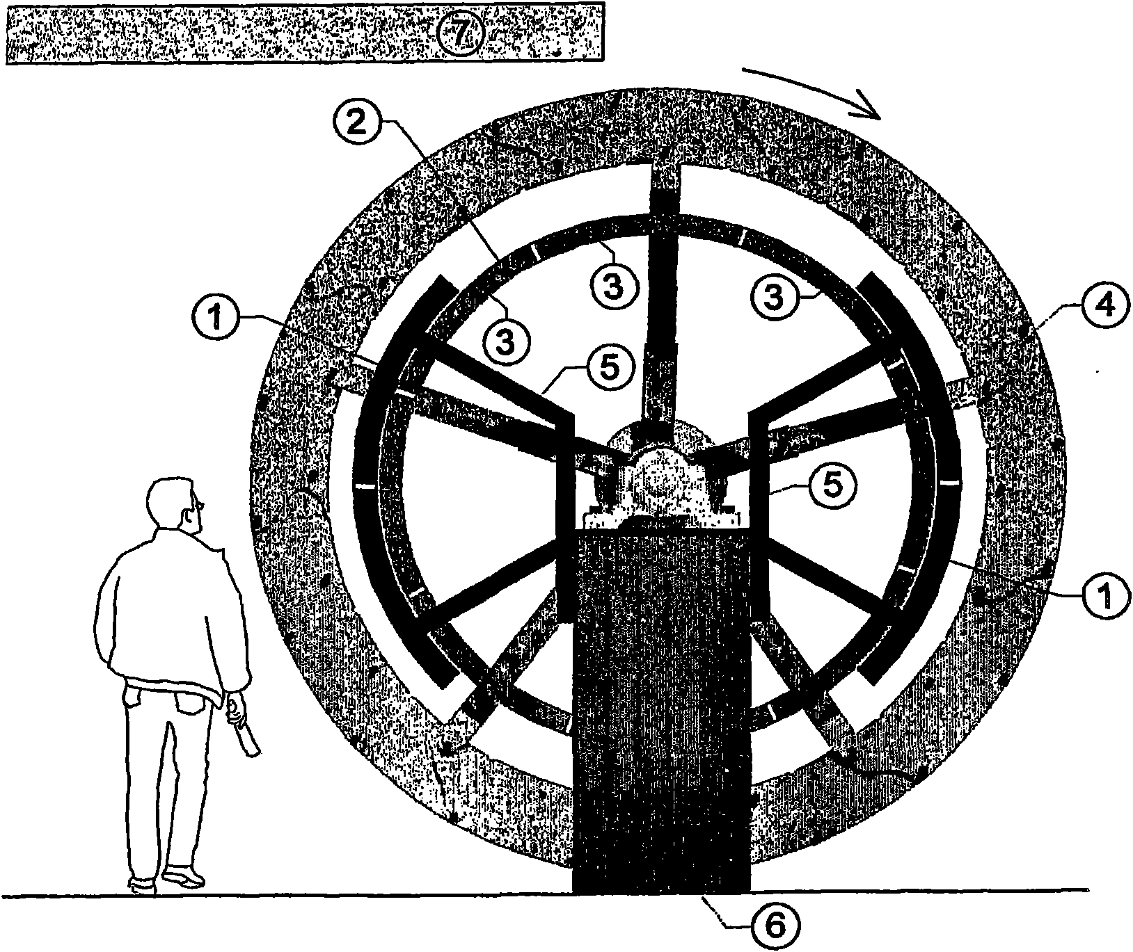
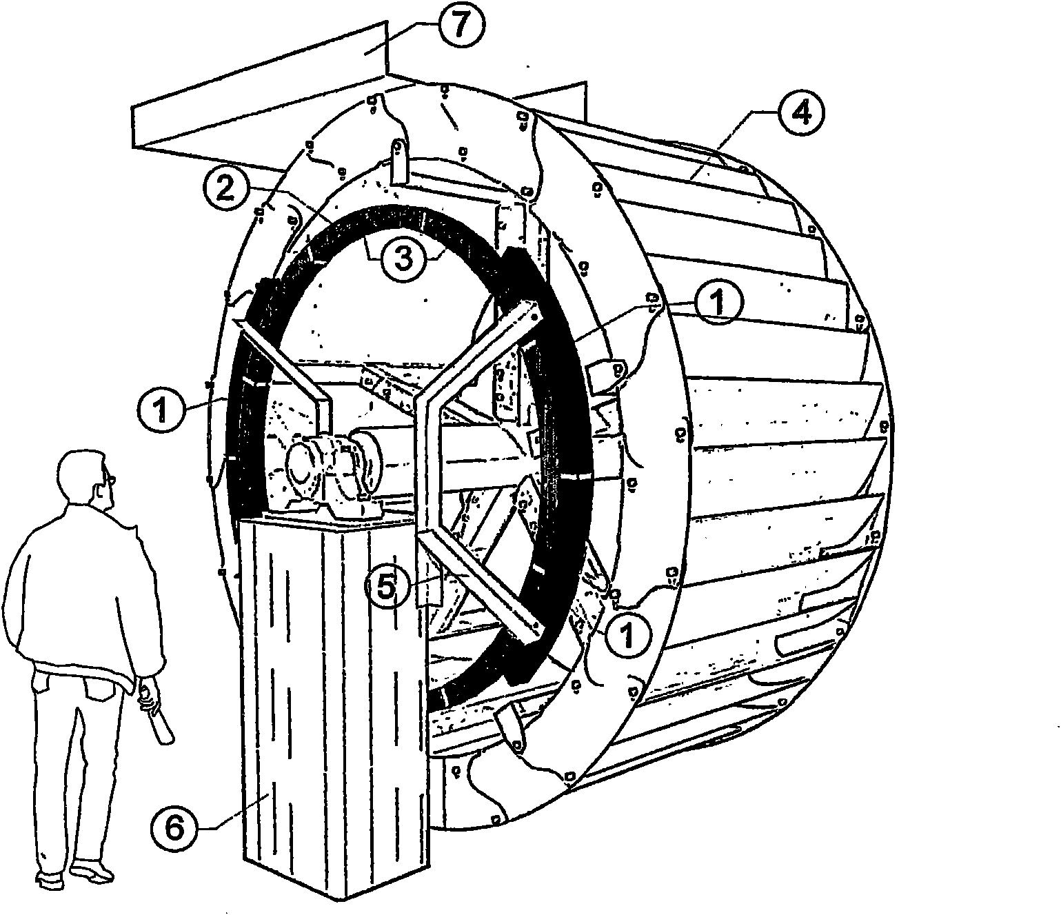
[0024] In the embodiment, water wheel 4 is provided, and they follow figure 2 , 3 and 8 are designed as an upper impact wheel 4 with a correspondingly assigned water supply channel 7 and are mounted in a known manner via a stationary base 6 . Water wheel 4 is here formed in this case from individual rim elements.

[0025] A ring generator is coupled to the water wheel 4 , which ring generator is formed by the rotor 2 as ring element and is fixedly connected to the water wheel 4 . Here it is connected to the spokes of the water wheel body or rests directly on the formed ring.

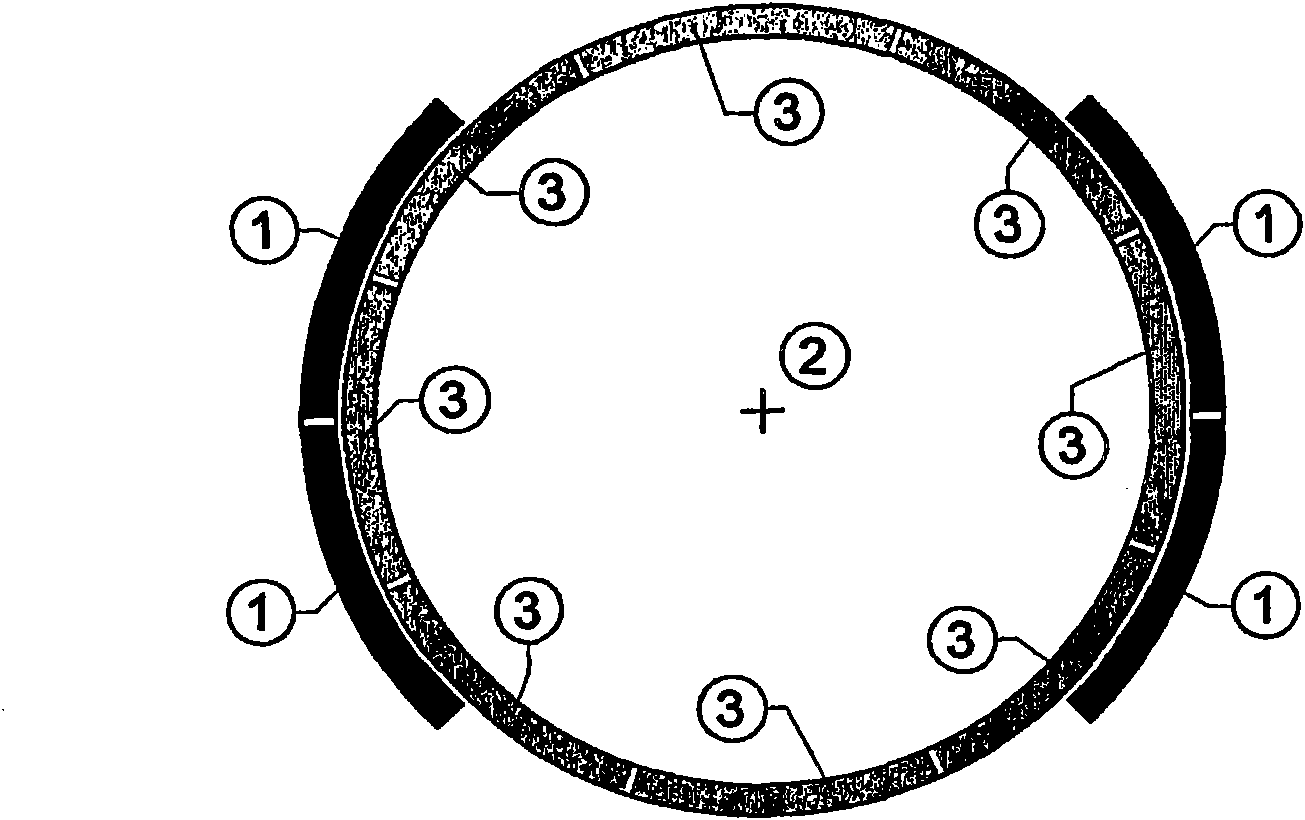
[0026] This annular element is composed in a modular manner as a rotor 2 of individual segments 3 equipped with corresponding permanent magnets 8 . High-power magnets are used here, such as those known under the trade name NEODYN magnets. These permanent magnets 8 are arranged in the exemplary embodiment on the front side, rear side, inner surface or outer surface of the ring element as the rotor 2 ...


PUM


Abstract

The invention relates to a water wheel comprising a built-in generator, a ring element being concentrically connected to the water wheel in a fixed manner. The ring element is composed of individual segments associated in a module comprising inserted permanent magnets. At least one corresponding partial ring acting as a stator is associated with the rotor formed in this way, the partial rings comprising electric coils associated with the permanent magnets of the ring element of the rotor. The partial rings forming a stator are arranged above supporting elements of the water wheel in a fixed manner by means of holding elements.

Description

technical field [0001] The invention relates to a water wheel with an integrated generator, which can be driven by flowing, projecting or free-falling water by means of correspondingly assigned water blades for generating electricity. Background technique [0002] Due to the function, the water wheel has a relatively low rotational speed with a high torque. For the purpose of generating electricity, therefore, a multistage mechanical transmission is usually journalled to the journal of the water wheel, and the output shaft of this transmission is connected to the generator via a transmission. [0003] When the water volume changes, especially when the water volume increases, the power and torque increase, so that the water wheel shaft and the transmission must receive relatively high peak torques. [0004] Therefore in practice a design of the components with a factor of 3 compared to the normal load is used. This results in relatively heavy and cost-intensive components. ...

Claims


Application Information

Patent Timeline
Patent Type & Authority Applications(China)
IPC IPC(8): F03B17/06F03B7/00
CPCF03B7/003F03B17/062F05B2220/706F05B2220/7066F05B2220/7068H02K7/1823H02K7/1869H02K21/24H02K41/03H02K2201/15Y02E10/20Y02E10/30F03B7/00F03B17/061
Inventor H·德鲁兹
Owner H·德鲁兹
Why Eureka
Try Eureka