
Projection system

A projection system and projection lens technology, applied in the field of projection systems, can solve the problems of increasing the size of the projection system, increasing material costs, and inconvenient control of the optical axis, and achieve the effects of simple structure, avoiding failure, and low cost

Inactive Publication Date: 2013-03-20
LG ELECTRONICS INC
View PDF15 Cites 0 Cited by
  • Summary
  • Abstract
  • Description
  • Claims
  • Application Information

AI Technical Summary

Problems solved by technology

[0004] However, this solution using prisms reduces brightness due to light loss that occurs when light passes through the boundaries of each glass structure constituting the prisms, increases the size of the projection system due to the use of prisms with a large volume, increases material Costly and difficult to assemble, inconvenient to control the optical axis accurately, and requires correction of the optical axis when the optical axis deviates during use, etc.

Method used

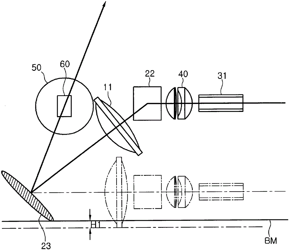
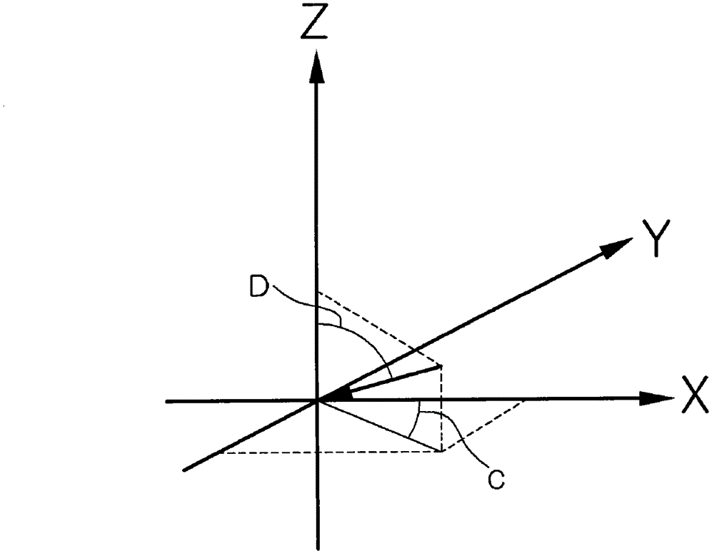

Image

  • Projection system
  • Projection system
  • Projection system

Examples


Embodiment Construction

[0016] Hereinafter, exemplary embodiments of the present invention will be described in detail with reference to the accompanying drawings.

[0017] However, the subject matter of the present invention is not limited to the following embodiments, but those skilled in the art who understand the subject matter of the present invention can easily propose various embodiments included in the scope of the same subject matter by adding, changing, omitting components, etc. These examples are to be understood as being included within the subject matter of the present invention.

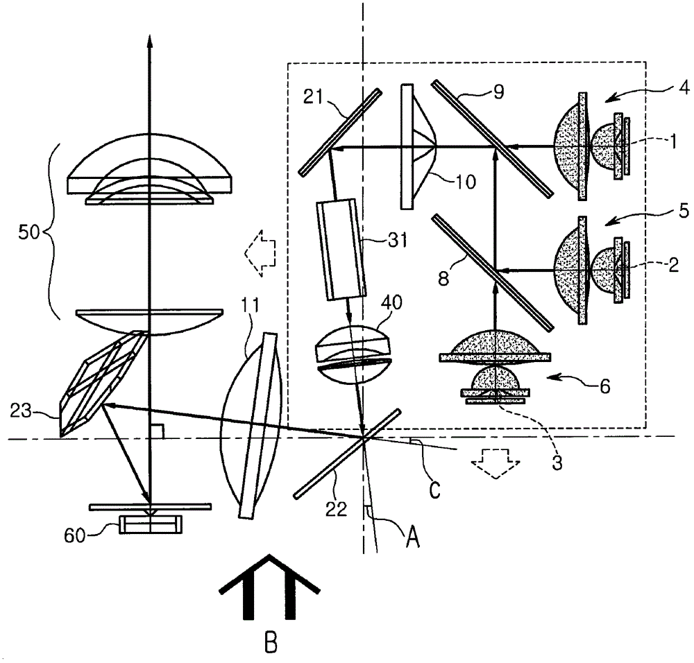
[0018] figure 1 is a structural view of a projection system according to an exemplary embodiment and shows a plan view.

[0019] refer to figure 1 , the projection system includes: a first light emitting device 1; a second light emitting device 2; a third light emitting device 3; collimators 4, 5 and 6, the collimators 4, 5 and 6 make the 3 concentrated emitted light; dichroic mirrors 8 and 9, which accurat...


PUM


Abstract

In order to obtain the following effects: that is, increase the brightness of the image, miniaturization, low cost, ease of operation, avoidance of failure, and ease of assembly. These effects can be obtained by a projection system comprising: at least one light-emitting device; time-divided light supply means, which time-divides light emitted from said at least one light-emitting device and supplies the light; a first condensing lens that concentrates light passing through the time-division supply device for light; a first reflector that reflects light passing through the first condensing lens; integrating an integrator, which makes the light reflected from the first mirror into a plane light; a second mirror, which reflects the light passing through the integrator; a third mirror, which The DMD side reflects the light reflected from the second reflector; and a projection lens that projects the light reflected from the second reflector onto a screen and has an optical axis, the second reflector and the third reflector The mirrors are respectively placed on both sides of the optical axis.

Description

technical field [0001] The invention relates to a projection system. Background technique [0002] A projection system is a device that carries image signals on light emitted from a light emitting device, projects the image signals on the front or rear surface of a screen, and allows a viewer to see them. For the projection system, there are CRT schemes, digital micromirror device schemes, Lcos schemes, transmissive LCD schemes, etc. according to operation schemes. [0003] As a conventional example of a projection system, there is WO 99 / 64912A1 (hereinafter referred to as cited document). This cited document discloses a scheme in which light emitted from red, green and blue light-emitting diodes is synthesized by a prism and transmitted to a display device such as an LCD display. Furthermore, the prism is placed around a display device (such as an LCD or DMD) forming image signals and used to synthesize these image signals. [0004] However, this solution using prisms re...

Claims


Application Information

Patent Timeline
Patent Type & Authority Patents(China)
IPC IPC(8): G03B21/14
CPCG03B21/2066G03B21/208H04N9/3111H04N9/3141G03B21/00G03B21/14
Inventor 金阳植尹赞永郑周永
Owner LG ELECTRONICS INC
Learn More