Ground processing system

A processing system and ground technology, applied in manual sweeping machines, suction filters, cleaning equipment, etc., can solve the problem of not being able to be removed from the charging stand, and achieve the effect of beautifying the living environment and effective living environment

Active Publication Date: 2014-06-25
ECOVACS ROBOTICS (SUZHOU ) CO LTD
View PDF5 Cites 0 Cited by
  • Summary
  • Abstract
  • Description
  • Claims
  • Application Information

AI Technical Summary

Problems solved by technology

Some charging bases are also equipped with a dust collection device. The dust collection device on the charging base will automatically start to collect the dust cleaned by the main body of the robot. However, the dust collection device on the charging base cannot be removed from the charging base. Works with charging stand

Method used


Image

  • Ground processing system
  • Ground processing system
  • Ground processing system

Examples


Embodiment 1

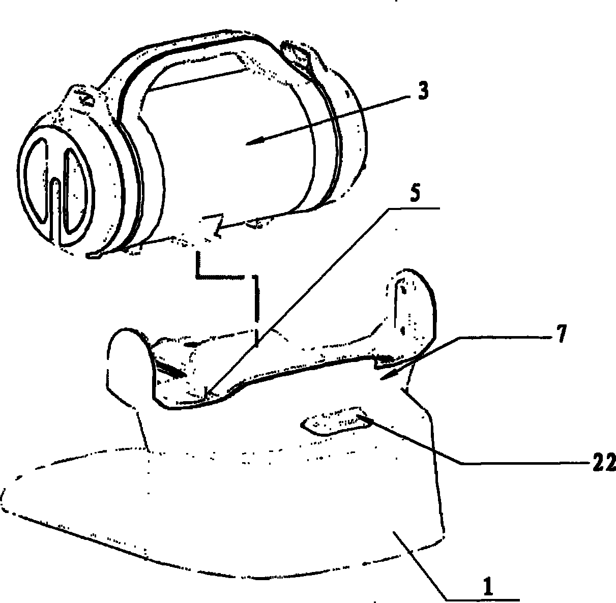
[0053] In the technical solution of this embodiment, the rotation of the transmission wheel is used to drive the pulley bracket and the locking piece, so that the locking piece is separated from the matching piece of the locking piece, so as to achieve the purpose of detaching the dust collection unit from the base.

[0054] Combine below Figure 4~5 The process of detaching the dust collection unit from the base body of the base will be described.

[0055] The release part 22 is affected by an external force and pulls the traction member 410. The transmission wheel bracket 403 is subjected to the traction force to pull the first transmission wheel 401 to rotate. The first transmission wheel 401 and the second transmission wheel 411 mesh with each other. Under the action of the first transmission wheel 401, The second transmission wheel 411 rotates thereupon, the first pulley bracket 406 is connected with the first transmission wheel 401 and the first locking member 404 respec...

Embodiment 2

[0060] In the technical solution of this embodiment, the rotation of the locking member bracket 203 is used to drive the first locking member 202 and the second locking member 212 to produce relative motion, so that the first and second locking members are respectively connected to the first and second locking members. The matching parts of the fastening parts are separated to achieve the purpose of detaching the dust collection unit 3 from the base body 7 .

[0061] Combine below Figure 7 The process of detaching the dust collection unit from the base body of the base will be described.

[0062] The release part 22 is acted by an external force to drive the first locking part 202 to move, so that the locking part bracket 203 rotates around the rotating shaft 210, and the second locking part 212 connected with the locking part bracket 203 moves accordingly, thereby respectively driving the first locking part 202 The first locking part 202 and the second locking part 212 are ...


PUM


Abstract

The invention belongs to the technical field of cleaning equipment and relates to a ground processing system which comprises a pedestal (1) and a surface processing device (2). The surface processing device (2) is set with a cleaning mode and an ash discharging mode; the surface processing device (2) comprises a shell and is internally provided with a dust collection unit (8); an ash outlet (9) is arranged on the shell; an ash discharging channel (6) is arranged in the pedestal (1); the ash discharging channel (6) is communicated with the dust collection unit (8) through the ash outlet (9); a basal body (7) and a dust collection unit (3) are arranged on the pedestal (1); an ash inlet (5) is arranged on the basal body (7); the ash inlet (5) is communicated with the dust collection unit (3); and the dust collection unit (3) is provided with a vacuum source; when the surface processing device (2) is under an ash discharging mode, the vacuum source is under a working state; then the dirt collected in the dust collection unit (8) passes through the ash discharging channel (6) through the ash outlet (9) under the suction effect of the vacuum source and enters the dust collection unit (3) from the ash inlet (5); and the dust collection unit (3) is mounted on the basal body (7) of the pedestal (1) in a separate way, and can be independently used. The ground processing system can beauty the living environments more conveniently and more effectively.

Description

technical field [0001] The invention belongs to the technical field of cleaning equipment and relates to a ground treatment system. After the dust collection unit of the system is separated from the base in the ground treatment system, the dust collection unit can be used independently. Background technique [0002] With the continuous improvement of living standards and technological capabilities, household service robots with various functions have gradually entered the homes of ordinary people, bringing convenience to people's lives to varying degrees. Among all kinds of home service robots, robots that treat surfaces such as people's home floors are the most popular. [0003] At present, most of the existing cleaning robots are equipped with a charging stand, and such a cleaning robot system at least includes a robot main body and a charging stand. The main body of the robot includes a casing, and a rechargeable battery and a control unit are arranged inside the casing....

Claims


Application Information

Patent Timeline
Patent Type & Authority Patents(China)
IPC IPC(8): A47L5/12A47L11/24A47L9/00A47L9/16
Inventor 吕小明
Owner ECOVACS ROBOTICS (SUZHOU ) CO LTD
Why Eureka
Try Eureka