
Drawing machine for internal-threaded pipe

A technology of internal threaded pipe and drawing machine, which is applied in the direction of heat exchange equipment, etc., achieves the effects of low cost, simple structure, and easy transportation and installation.

Active Publication Date: 2013-09-04
JIANGSU XINGRONG HI TECH
View PDF4 Cites 0 Cited by
  • Summary
  • Abstract
  • Description
  • Claims
  • Application Information

AI Technical Summary

Problems solved by technology

But there are following defects in adopting this inverted drawing method: (1), the inverted drawing machine that this drawing method uses is complicated in structure, and manufacturing cost is high, and volume is big
But this V-groove drawing method has the following defects: (1) the drawing force is small, easy to slip, and the drawing efficiency is low
Since there is a V-shaped groove on the drawing cylinder, this drawing method allows only 3 / 4 turns of internal threaded pipe to be wound on the drawing cylinder with V-shaped groove (see Figure 5), that is, the internal thread pipe enters from the H end of the internal thread pipe inlet end, The I end of the outlet end of the internal threaded pipe is away from the drawing cylinder, so it cannot have several turns wound on the drawing cylinder to provide sufficient pulling force like the inverted drawing, so the drawing force is small and prone to pull. The phenomenon of slipping and stopping during drawing has a serious impact on the drawing rate and quality
(2), easy to deform, poor quality
In order to provide a large drawing force, the drawing machine with V-groove used in V-groove drawing is generally designed with multiple pinch rollers 6. , and the pressing force F should also be large (see Figure 6), but too much pressing force F will increase the ellipticity of the internal thread pipe (see Figure 7), that is, the value of e-f increases, so this kind of V-shaped groove drawing will cause the deformation of the internal thread pipe to increase, such as when drawing a 9.52 internal thread pipe, Its e-f value reaches about 0.5mm
In particular, the thinner the wall of the internally threaded pipe, the worse the ability of the internally threaded pipe to resist the compressive force F without producing an ellipse. The ellipticity index of the pipe is seriously exceeded, which cannot meet the drawing quality requirements, and is prone to waste products; in addition, long-term drawing will also cause wear at the contact point P between the internal threaded pipe and the V-shaped groove, which will cause the drawn internal threaded pipe to produce Scratches will affect the appearance quality of subsequent drawing and internal threaded pipes

Method used


Image

  • Drawing machine for internal-threaded pipe
  • Drawing machine for internal-threaded pipe
  • Drawing machine for internal-threaded pipe

Examples


Embodiment 1

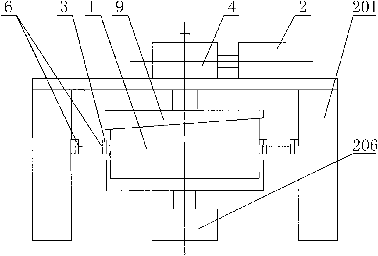
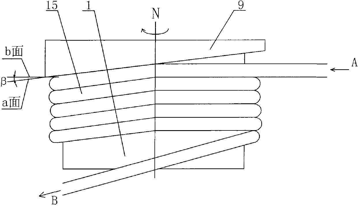
[0033] Such as Figure 8 and Figure 9 As shown, a method for drawing an internally threaded pipe, the internally threaded pipe 15 is wound several times on the outer surface of the drawing cylinder 1, the C end of the internally threaded pipe is at the bottom, and the D end of the internally threaded pipe is at the top. The pressure roller 6 is pressed against the outer diameter of the internally threaded pipe 15, so that the internally threaded pipe 15 is close to the drawing cylinder 1. During the drawing process, the power device 2 drives the drawing cylinder 1 and the discharge cylinder 1 through the transmission device 4. The ring 9 rotates, and the discharge ring 9 is continuously discharged upward on the drawing cylinder 1 .

[0034] Such as Figure 8 to Figure 12 As shown, an internally threaded pipe drawing machine for realizing the above-mentioned internally threaded pipe drawing method includes a drawing cylinder 1, a power device 2, a pressure roller device 3, a...

Embodiment 2

[0043] The drawing method of this embodiment is the same as that of the first embodiment.

[0044] This embodiment is basically the same as the internally threaded pipe drawing machine in Embodiment 1, except that the radial gap δ in this embodiment is 0.8 mm, and the included angle α is 0.1°.

Embodiment 3

[0046] The drawing method of this embodiment is the same as that of the first embodiment.

[0047] This embodiment is basically the same as the internally threaded pipe drawing machine in Embodiment 1, except that the radial gap δ in this embodiment is 1.2mm, and the included angle α is 1.5°.


PUM


Abstract

The invention relates to a method for drawing an internally threaded pipe and its drawing machine. The method of the invention is to wind the internally threaded pipe several times on the outer surface of the drawing cylinder of the drawing machine. Below, the outlet end D of the internally threaded pipe is on the top, and the pressure roller is pressed against the outer diameter of the internally threaded pipe, so that the internally threaded pipe is close to the drawing cylinder. During the drawing process, the power device drives the drawing through the transmission device. The cylinder and the discharge ring rotate, and the discharge ring is continuously arranged upward on the drawing cylinder; the device of the present invention includes a discharge tray (7) and a leg device (16), and the outer surface of the drawing cylinder (1) is A smooth cylinder, the discharge ring (9) is arranged on the lower side of the outside of the drawing cylinder (1), there is a radial gap δ between the inner diameter of the discharge ring (9) and the outer diameter of the drawing cylinder (1), and the discharge There is an angle α between the discharge surface of the material ring (9) and the horizontal plane. The invention has the advantages of low cost, convenient arrangement, good drawing quality, large drawing force and high drawing efficiency.

Description

technical field [0001] The invention relates to a drawing method and a drawing device thereof, in particular to an internal thread pipe drawing method and a drawing machine thereof, and belongs to the field of metal pipe processing and manufacturing. Background technique [0002] The inner threaded tube is a high-efficiency and energy-saving heat exchange tube. The inner threaded tube is formed on the inner wall of the traditional light tube by drawing and spinning to form a set of helical tooth grooves with a certain shape and a certain depth. This group of spiral tooth grooves can not only increase the inner surface area of ​​the pipe, but also can effectively stir the fluid and increase the turbulence effect of the fluid in the pipe. Compared with the plain pipe of the same specification, the internal thread pipe can improve the heat exchange capacity of the pipe by 30 %above. Therefore, internally threaded pipes have been widely used in refrigeration industries such as...

Claims


Application Information

Patent Timeline
Patent Type & Authority Patents(China)
IPC IPC(8): B21C1/24B21C1/32B21D53/06
Inventor 周逵肖克建孙志伟朱建秋高峰
Owner JIANGSU XINGRONG HI TECH
Learn More