Angle steel relieving back-gouging machine

A back-shoveling and root-clearing technology, which is applied in the direction of metal processing machinery parts, clamping, supporting, etc., can solve the problems of high labor intensity of fixtures, low overall efficiency, and high cost of milling machines, and achieves simple structure, wide applicability, and low cost. low effect

Inactive Publication Date: 2011-10-19
贺自清
View PDF5 Cites 13 Cited by
  • Summary
  • Abstract
  • Description
  • Claims
  • Application Information

AI Technical Summary

Problems solved by technology

[0002] At present, the shovel back and root cleaning of angle steel are usually processed by planer, which is low in efficiency, and some are processed by general milling machines, but the cost of general milling mach

Method used


Image

  • Angle steel relieving back-gouging machine
  • Angle steel relieving back-gouging machine
  • Angle steel relieving back-gouging machine

Examples


no. 1 example

[0017] In the first embodiment:

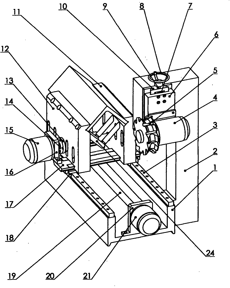
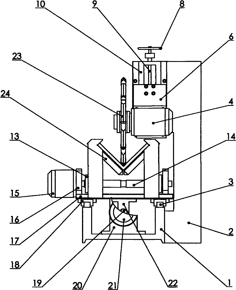
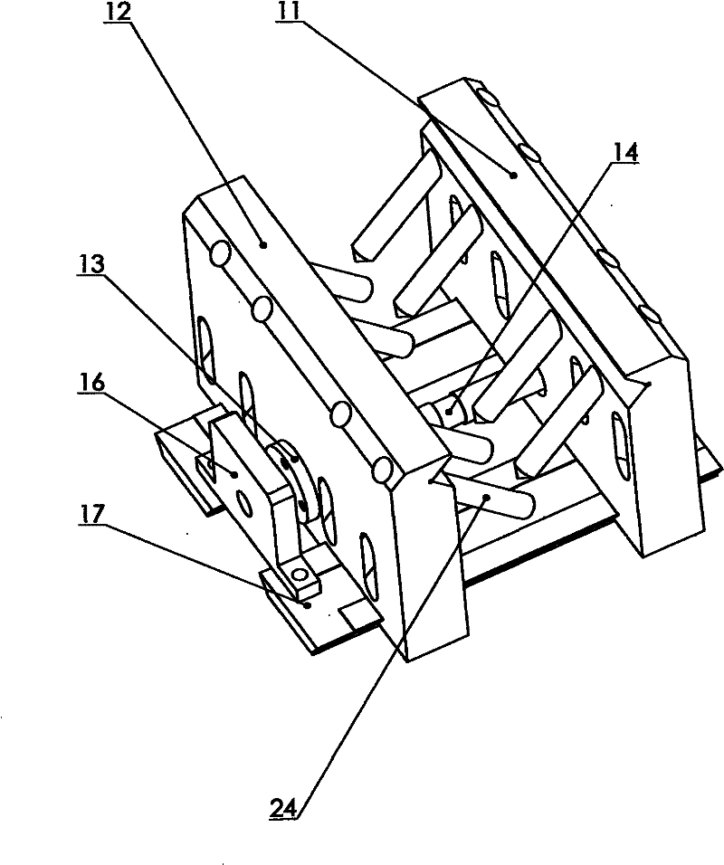
[0018] figure 1 It is a perspective view of the angle steel shovel back root cleaning machine at the shovel back station, attached figure 2 It is the right view of the root cleaning station of the angle steel shovel back cleaning machine, attached image 3 It is a perspective view of the right jaw and left jaw of the angle steel shovel backrooting machine. In the three views listed, the main screw 19 is fixed on the bed 1 through the main bearing housing 20, one end of the main screw 19 is connected to the main reduction motor 21, and the main screw nut 22 screwed on the main screw 19 is fixed. On the clamping dovetail 17, the clamping dovetail 17 is fixed on the slide block 18 matched with the linear guide rail 3, and the linear guide rail 3 is fixed on the bed 1. The clamp screw rod 14 is fixed on the clamping dovetail 17 through the bearing seat 16, one end of the clamp screw rod 14 is connected to the clamping reduction motor 15, and a...


PUM


Abstract

The invention relates to an angle steel relieving back-gouging machine, which comprises a lathe body (1), a machine frame (2), a straight guide rail (3), a milling deceleration motor (4), a relieving milling cutter (5), an adjusting dovetail groove (6), an adjusting nut (7), a handwheel (8), an adjusting screw (9), an adjusting dovetail (10), a right jaw (11), a left jaw (12), a clamp nut (13), a clamp screw (14), a clamping deceleration motor (15), a clamping bearing pedestal (16), a clamping dovetail (17), a slide block (18), a main leading screw (19), a main bearing pedestal (20), a main deceleration motor (21), a main nut (22), a back-gouging milling cutter (23), and a railing (24). The right jaw (11) and the left jaw (12) can rapidly clamp an angle steel opening upwardly or downwardly by the driving of the clamping deceleration motor (15), and the angle steel is processed by relieving through the relieving milling cutter or is processed by back-gouging through the back-gouging milling cutter. The invention has the advantages of extensive applicability, low labor intensity for workers, simple operations, rapid relieving and back-gouging speed, high efficiency, simple structure, low cost, and convenient maintenance.

Description

technical field [0001] The invention relates to an angle steel processing machine, in particular to an angle steel shovel back root cleaning machine. Background technique [0002] At present, the shovel back and root cleaning of angle steel are usually processed by planer, which is low in efficiency, and some are processed by general milling machines, but the cost of general milling machines is high, and different fixtures are required for root cleaning milling and shovel back milling, and manual operation of the fixtures is labor intensive. , the speed is slow, and the overall efficiency is not high. Contents of the invention [0003] The object of the present invention is to provide a kind of angle steel shovel back root cleaning machine aiming at above-mentioned deficiencies in the prior art, and this angle steel shovel back root cleaning machine has the characteristics of convenient operation and high efficiency. [0004] The technical solution of the present inventio...

Claims


Application Information

Patent Timeline
IPC IPC(8): B23C3/00B23Q3/06
Inventor 贺自清
Owner 贺自清
Why Eureka
Try Eureka