
All-fiber mantle-mobile hot air circulation annealing furnace

A hot air circulation and annealing furnace technology, applied in furnaces, heat treatment furnaces, furnace types, etc., can solve problems such as cost increase, inability to process in the same furnace, and investment increase, so as to reduce energy and cost, improve heat treatment efficiency, and ensure production progress Effect

Inactive Publication Date: 2011-10-19
SHANGHAI BAOSTEEL EQUIP MAINTENANCE CO LTD
View PDF5 Cites 3 Cited by
  • Summary
  • Abstract
  • Description
  • Claims
  • Application Information

AI Technical Summary

Problems solved by technology

From the above, it can be seen that this annealing furnace cannot adjust the cavity of the furnace body depending on the size of the workpiece, and the heat treatment operation can only be performed in a large cavity of the furnace body for small workpieces; if conditions permit, multiple annealing furnaces can be equipped, depending on the size of the workpiece, Place the workpiece in a suitable annealing furnace for heat treatment; when the annealing furnace is limited, only small workpieces can be placed in a large annealing furnace, or large workpieces can be processed outsourced; obviously, the above will increase investment, waste energy or cost improvement
In addition, when the heat treatment temperature of the workpiece is different, it cannot be processed in the same furnace, which also causes a waste of energy and affects the production schedule and heat treatment efficiency.

Method used


Image

  • All-fiber mantle-mobile hot air circulation annealing furnace
  • All-fiber mantle-mobile hot air circulation annealing furnace
  • All-fiber mantle-mobile hot air circulation annealing furnace

Examples


Embodiment Construction

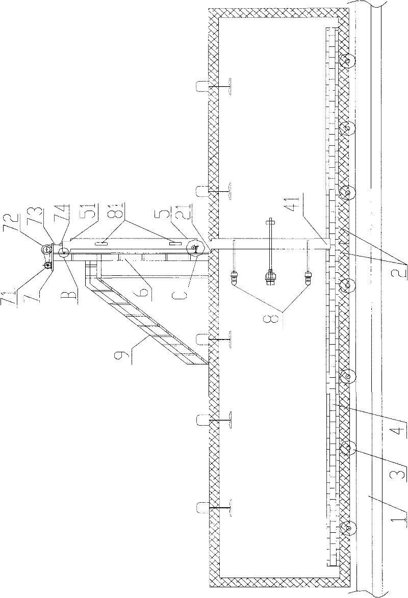
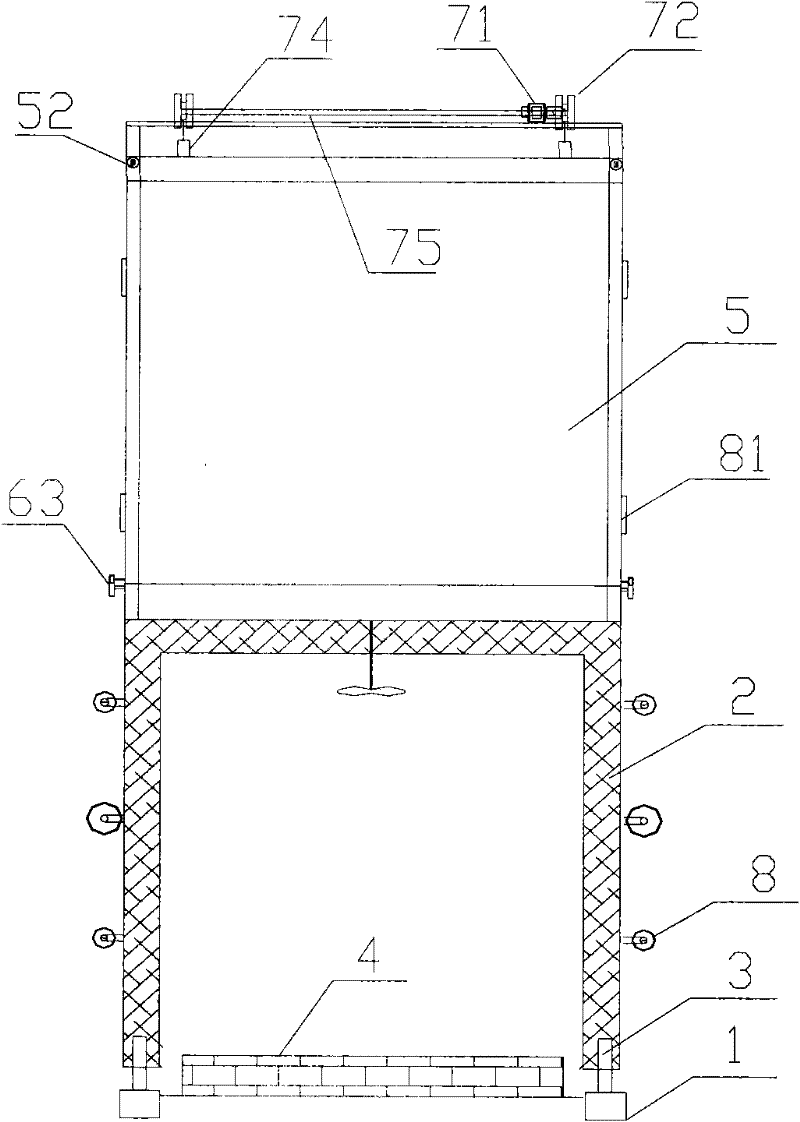
[0017] Such as figure 2 and image 3 As shown, the all-fiber hood mobile hot air circulation annealing furnace of the present invention includes two furnace hoods 2 arranged on guide rails 4 through rollers 3 and a furnace platform 4 located in the furnace hood 2, and also includes a furnace gate 5, two Lifting lug 74, two vertical rods 6, platform 7, four pull rods 8, four handles 81, two transmission wheels 72 and motor 71, the two vertical rods 6 are vertically arranged on the top surface of any one of the furnace cover 2 On both sides of the furnace mouth, the platform 7 is horizontally arranged on the tops of the two vertical rods 6, the motor 71 and the two transmission wheels 72 are respectively arranged on both sides of the platform 7, and the two transmission wheels 72 pass through the rotating shaft 75 connection, the two lifting lugs 74 are arranged on the top surface of the furnace gate 5 at intervals, the two lifting lugs 74 are connected to the two transmission...


PUM


Abstract

The invention discloses an all-fiber mantle-mobile hot air circulation annealing furnace, and is characterized in that: two mantles are located on a guide rail by two rollers, a furnace platform is positioned in the two mantles, two poles are located at two sides of the top mouth of any mantle, a platform is horizontally arranged at the tops of the two poles, a motor and a transmission wheel are separately located at both sides of the platform, two lifting lugs are located at the furnace gate top at a certain interval and are connected with the transmission wheel through a steel wire, the rotation shaft of the motor drives the transmission wheel through a belt, the furnace gate rises or descends along the mantle mouth through the motor and transmission wheel, a groove is opened on the furnace platform surface, the furnace gate is located in the groove when the furnace gate descends to the furnace platform, two pull rods are located at the sides of the mantle with the two poles at a certain interval, and two pull pieces are located at a side of the furnace gate at a certain interval, matching with the two pull rods. The annealing furnace can economically implement the heat treatment of the parts with different sizes at different temperature, avoid the investment in arranging multiple annealing furnaces, reduce energy consumption and cost for heat treatment, guarantee the production schedule and improve the heat treatment efficiency.

Description

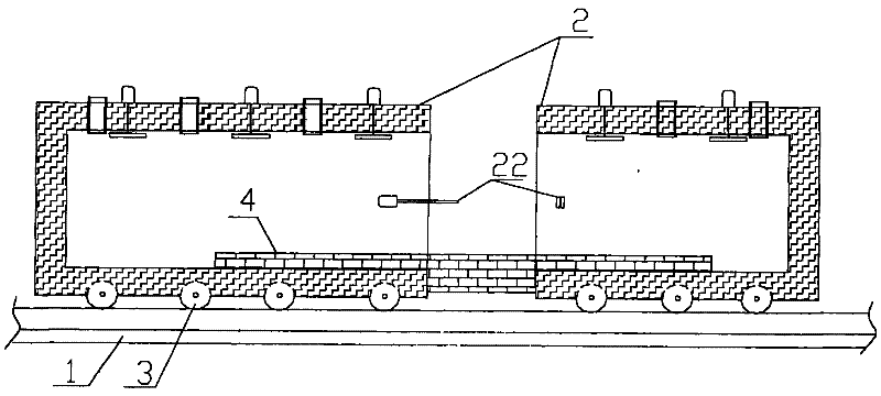
technical field [0001] The invention relates to an all-fiber furnace cover mobile hot air circulation annealing furnace. Background technique [0002] The furnace cover mobile hot air circulation annealing furnace is widely used in heat treatment production. The annealing furnace has high requirements for working conditions, and its temperature uniformity is ≤±10°C. ≤50°C. To achieve a furnace temperature uniformity of ≤±10°C, the furnace body must have extremely high airtightness. Such as figure 1 As shown, it generally includes two guide rails 1 parallel to the ground, two furnace covers 2 provided with rollers 3, a furnace cover pull rod pull 22 and a furnace platform 4 respectively arranged at the furnace mouth of the two furnace covers 2, and the furnace platform 4 is fixed. Located on the ground between the two guide rails 1, the two furnace covers 2 are set on the two guide rails 1 through the rollers 3 and move towards each other along the guide rails 1. When the ...

Claims


Application Information

Patent Timeline
Patent Type & Authority Applications(China)
IPC IPC(8): C21D9/00C21D1/26
Inventor 徐新华
Owner SHANGHAI BAOSTEEL EQUIP MAINTENANCE CO LTD
Learn More