Speaker Diaphragm

a diaphragm and speaker technology, applied in the direction of diaphragm construction, fibre diaphragm, non-planar diaphragm/cone, etc., can solve the problems of partial cancellation of the sound from said portions, poor regenerated sound quality, and elasticity of ordinary diaphragm per s

Inactive Publication Date: 2008-01-31
PANASONIC CORP +1
View PDF3 Cites 20 Cited by
  • Summary
  • Abstract
  • Description
  • Claims
  • Application Information

AI Technical Summary

Problems solved by technology

Elasticity of ordinary diaphragms per se will however give rise to a certain problem.
In a certain range of input frequencies, those peripheral and central portions are likely to vibrate at reversed phases, thereby causing partial cancellation of the sounds from

Method used


Image

  • Speaker Diaphragm
  • Speaker Diaphragm
  • Speaker Diaphragm

Examples


examples

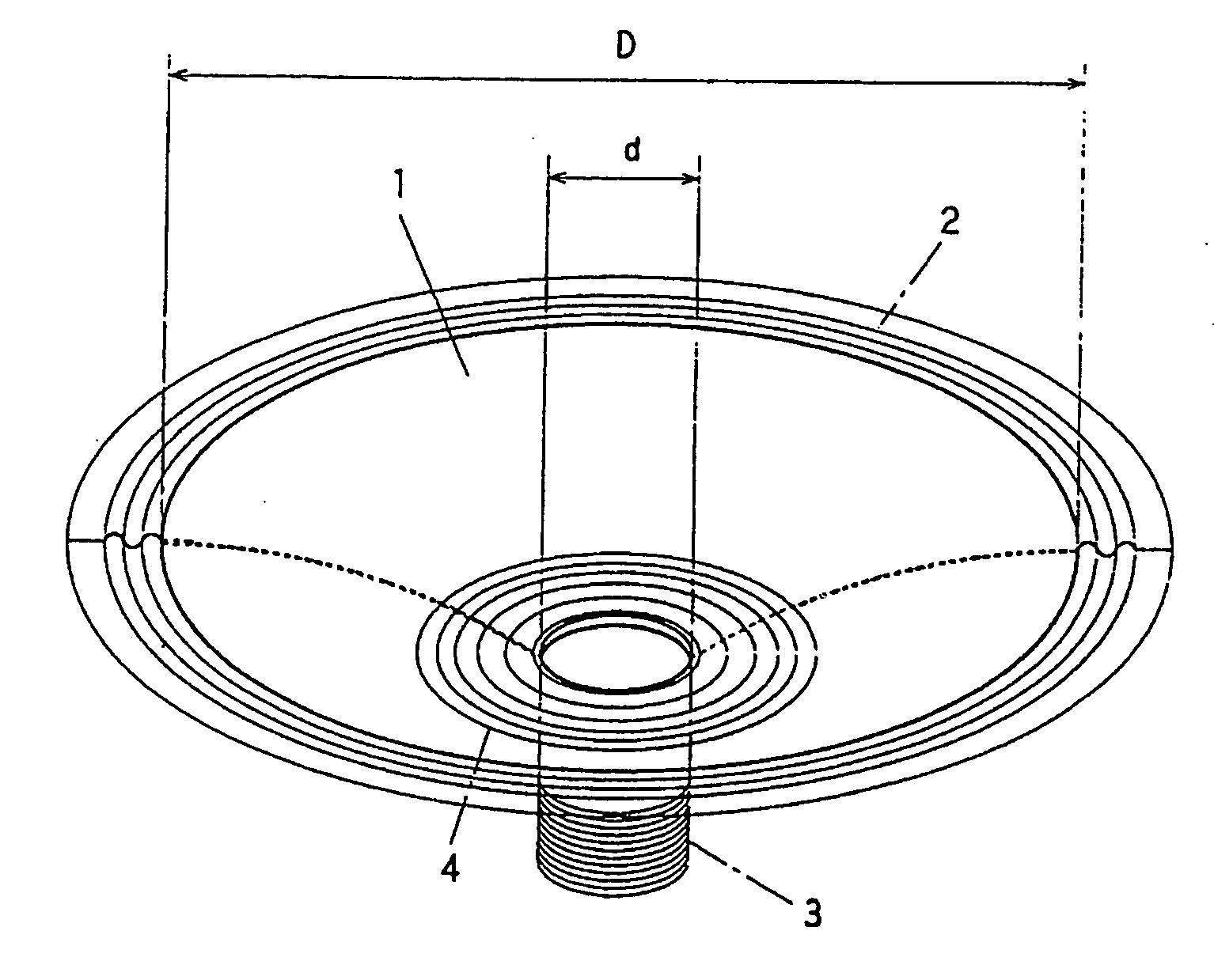
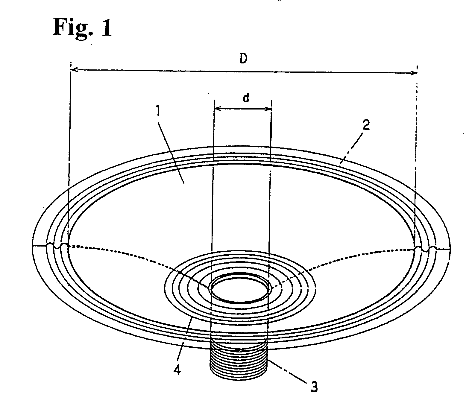
[0021]FIG. 1 illustrates EXAMPLE 1 of the present speaker diaphragm shown in its perspective outlook. The diaphragm 1 provided as the EXAMPLE 1 is of the so-called cone type having a conical appearance with a somewhat curved generatrix. Its outer periphery is connected by a discrete edge 2 (usually called free edge) to the inside of a frame (not shown). Attached by an annular connector to the central portion of this diaphragm is a voice coil 3, and this connector is a damper 4 that is likewise fixed on the inside of said frame.

[0022]The speaker diaphragm 1 of EXAMPLE 1 is composed of: (1) a polypropylene resin as the non-chlorinated resin, (2) a wood powder as the cellulose powder having an average particle size of 200 μm, and 100 weight parts of this powder having been surface-esterified using 10 weight parts of maleic anhydride, and (3) benzoyl peroxide as the organic peroxide. 49.5% by weight of the polypropylene resin, 50% by weight of the wood powder and 0.5% by weight of benzo...


PUM

PropertyMeasurementUnit
Temperatureaaaaaaaaaa
Fractionaaaaaaaaaa

Abstract

A smaller-sized and acoustically excellent speaker diaphragm is inexpensively provided using the mixture of a specially surface-coated woody material and a mass-producible synthetic resin.
The mixture is composed of a non-chlorinated synthetic resin and a powdery cellulose material whose particle size falls within a range of from 5 μm to 500 μm. The cellulose material has been subjected to a surface treatment to enhance its affinity to the non-chlorinated synthetic resin, and 30% to 70% by weight of the cellulose material is contained in the mixture.

Description

TECHNOLOGICAL FIELD OF THE INVENTION[0001]The present invention relates to the structure of a speaker diaphragm that constitutes a speaker serving as an instrument for putting out therefrom regenerated sound waves.BACKGROUND ART[0002]As well known in the art, the conventional speaker devices have each comprised two principal parts, that is an electromechanical transducer and a diaphragm combined therewith. The transducer converts the electrical energy of electric signals into mechanical vibration energy, and this vibration energy output from the transducer does activates in turn the diaphragm to vibrate itself and radiate an audio or the like acoustic energy. FIG. 1 schematically shows the structure of an example of such a diaphragm together with other relevant and adjacent parts. A voice coil 3 is attached to the central portion of the diaphragm 1, with a flexible diaphragm edge 2 being secured to the outer periphery of this diaphragm. A flexible damper 4 also flexible is connected...

Claims


Application Information

Patent Timeline
IPC IPC(8): H04R7/02
CPCC08L1/10C08L23/02C08L23/10C08L97/02H04R7/02H04R7/12H04R2307/021H04R2307/029C08L2666/06C08L2666/26C08K5/14
Inventor ISHIDA, HIROYUKITAKAHASHI, KENSUZUKI, TAKASHIOMORI, TATSUYAMIZONE, SHINYAMURAKAMI, KOICHIKISHIUE, KIYOSHI
Owner PANASONIC CORP
Why Eureka
Try Eureka