Fuel oil atomization device of smelting furnace burner

A fuel atomization and burner technology, applied in the direction of combustion method, combustion type, etc., can solve the problems of insufficient combustion of heavy oil, high cost of heavy oil use, and poor atomization effect.

Inactive Publication Date: 2011-10-19
必成玻璃纤维(昆山)有限公司
View PDF9 Cites 1 Cited by
  • Summary
  • Abstract
  • Description
  • Claims
  • Application Information

AI Technical Summary

Problems solved by technology

[0002] In the production of glass fiber, heavy oil and natural gas are used to heat the furnace. In the existing production process, steam is used to atomize the heavy oil. Because the steam conta...

Method used


Image

  • Fuel oil atomization device of smelting furnace burner
  • Fuel oil atomization device of smelting furnace burner
  • Fuel oil atomization device of smelting furnace burner

Examples


Embodiment 1

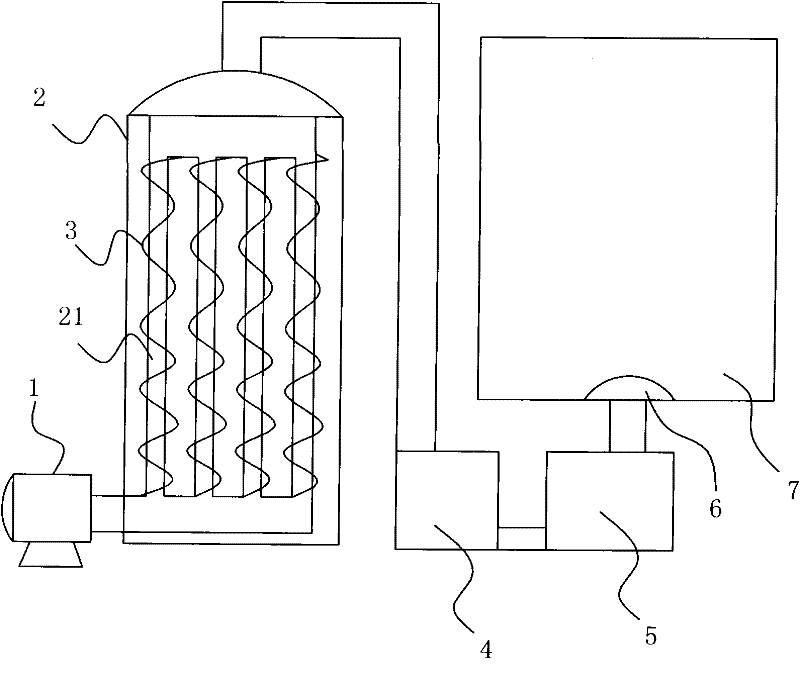
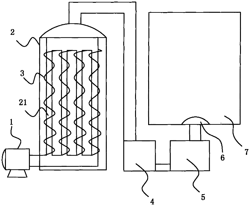
[0014] Example 1, such as figure 1 As shown, a fuel atomization device for a furnace burner includes an air intake fan 1, an air heater, an air dryer 4, an atomizing nozzle 6, a supercharger 5 and a furnace burner 7 connected together through pipelines, and the air The heater includes an air heating chamber 2 and a heater arranged in the air heating chamber 2 , and the heater is composed of a heating air pipe 21 and an electric heating wire 3 wound on the heating air pipe 21 .

[0015] The working principle is: the external air passes through the air intake fan 1 and enters the heating air pipe 21 in the air heater. After being heated by the electric heating wire 3, it enters the air dryer 4 for drying, and then enters the atomization after being pressurized by the supercharger 5 The nozzle 6 atomizes the heavy oil, and then ignites the atomized heavy oil sprayed into the furnace burner 7 to start the production of the furnace.

Embodiment 2

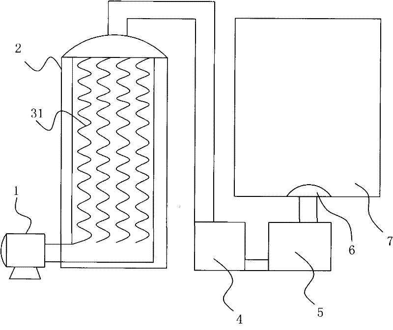
[0016] Example 2, such as figure 2 As shown, others are the same as in Embodiment 1, except that the heater is a heating tube 31 placed in the air heating chamber 2, and the heating tube 31 heats the air passing through the air intake fan 1 into the air heater , the heated air enters the air dryer 4 to dry, then pressurizes through the supercharger 5 and enters the atomizing nozzle 6 to atomize the heavy oil, and then ignites the atomized heavy oil sprayed into the furnace burner 7 to start the production of the furnace. The heating pipe 31 is composed of an insulating jacket and an electric heating wire passing through the insulating jacket, and the insulating jacket may be a ceramic tube or an asbestos coiled tube.

[0017] In the above embodiment, the external air can also be passed into the dryer 4 by the intake fan 1 for drying, then enter the air heating chamber 2 for heating, and finally enter the atomizing nozzle 6 to mist the heavy oil after being pressurized by the ...


PUM


Abstract

The invention discloses a fuel oil atomization device of a smelting furnace burner, comprising an atomization nozzle and a supercharger as well as an air inflow fan, an air heater and an air dryer connected together by pipelines, wherein the air heater comprises an air heating chamber and a heater arranged in the air heating chamber, and the heater comprises a heating air pipe and an electric heating strip wound on the heating air pipe or a heating pipe arranged in the air heating chamber. By adopting the technical scheme, the fuel oil atomization device has the beneficial effects that as air after being heated and dried is adopted for atomizing heavy oil, the atomizing effect is better, the heavy oil can be burned more completely, the unit heat conversion rate of the heavy oil is enhanced, and the using cost of the heavy oil is lower.

Description

technical field [0001] The invention relates to a fuel atomizing device for a furnace burner, in particular to a fuel atomizing device for a furnace burner used in the glass fiber industry. Background technique [0002] In the production of glass fiber, heavy oil and natural gas are used to heat the furnace. In the existing production process, steam is used to atomize the heavy oil. Because the steam contains high moisture, the atomization effect is not good, resulting in insufficient combustion of the heavy oil and heat conversion per unit of heavy oil. The rate is lower, and the cost of heavy oil is higher. Contents of the invention [0003] In order to solve the above problems, the object of the present invention is to provide a furnace burner fuel oil atomization device, which can enhance the atomization effect of heavy oil, improve the unit heat conversion rate of heavy oil, and reduce the use cost of heavy oil. [0004] In order to achieve the above object, the tech...

Claims


Application Information

Patent Timeline
IPC IPC(8): F23D11/44
Inventor 周登峰
Owner 必成玻璃纤维(昆山)有限公司
Why Eureka
Try Eureka