
Liquid level measurement method based on magnetic coupling and optical fiber pair array

A liquid level measurement and optical fiber pair technology, applied in the field of sensors, can solve the problems of blocking the movement of the baffle, the light cannot pass through, and the fouling of the baffle, so as to achieve the effect of wide application, elimination of interference, and accurate and reliable measurement.

Inactive Publication Date: 2012-07-04
WUHAN UNIV OF TECH
View PDF1 Cites 4 Cited by
  • Summary
  • Abstract
  • Description
  • Claims
  • Application Information

AI Technical Summary

Problems solved by technology

This invention is not suitable for the measurement of highly corrosive liquids because the baffles, fiber holders, and fiber end faces are directly immersed in the liquid.
And there is liquid between the end faces of the two optical fibers, so it cannot be used for the measurement of non-transparent liquids
In addition, baffles, fiber holders, fiber end faces, etc. are in direct contact with liquid and air, and are easily polluted, which will encounter many problems in actual measurement, such as: the fiber end face is polluted, causing light to not pass through; the baffle and fiber Fouling on the fixing seat and the groove, causing the movement of the baffle to be blocked, etc.

Method used


Image

  • Liquid level measurement method based on magnetic coupling and optical fiber pair array
  • Liquid level measurement method based on magnetic coupling and optical fiber pair array
  • Liquid level measurement method based on magnetic coupling and optical fiber pair array

Examples


Embodiment Construction

[0022] The present invention will be further described below in conjunction with the embodiments and accompanying drawings, but is not limited to the content described below.

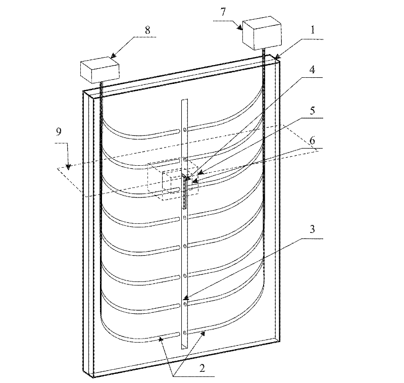
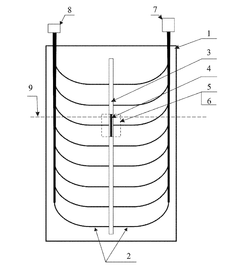
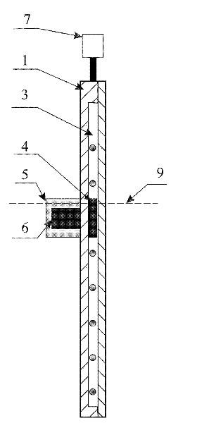
[0023] The liquid level measurement method based on magnetic coupling and optical fiber pair array provided by the present invention is realized by preparing a corresponding liquid level measurement sensor. The structure of the liquid level measurement sensor is as follows figure 1 As shown: it is mainly composed of a column 1, an optical fiber pair 2, a narrow slot guide groove 3, a magnetic light barrier 4, a float 5, a permanent magnet 6, a light source 7 and a light detector 8.

[0024] The column 1 is used to support the pair of optical fibers 2, and seal the pair of optical fibers 2 and the magnetic light barrier 4 inside the column to isolate it from the liquid to be measured. The column is made of polytetrafluoroethylene material. The shape and height of the column are designed according to the...


PUM


Abstract

The invention relates to a liquid level measurement method based on magnetic coupling and an optical fiber pair array. The method is characterized in that a stanchion is fixedly arranged in liquid; optical fiber pair linear arrays are arranged in the stanchion; narrow slits which can ensure light to pass are arranged between two optical fibers of each fiber pair; all the narrow slits are communicated to form a narrow slit guide slot; the narrow slit guide slot is internally provided with a magnetic light barrier; a buoy floating on the liquid surface is internally provided with a permanent magnet; the permanent magnet drives the magnetic light barrier to move along the narrow slit guide slot by the magnetic coupling, thus modulating the light flux of the fiber pair; according to differentliquid levels, the light flux of different fiber pairs can be modulated; and the liquid level position can be obtained by detecting the light flux of the fiber pairs. In the invention, the permanent magnet is sealed in the buoy; all the fiber pairs and the magnetic light barriers are sealed in the stanchion; and only the buoy and the stanchion are directly contacted with the liquid; therefore, aslong as the buoy and the stanchion are made of an anti-corrosive material according to the liquid to be detected, the method can be used for measuring the liquid level of any liquid.

Description

technical field [0001] The invention relates to the field of sensors, in particular to a liquid level sensor which uses magnetic coupling technology and optical fiber technology combined with a special structure to monitor the liquid level position of any liquid. Background technique [0002] Liquid level measurement involves all aspects of industrial and agricultural production and social life. Due to its intrinsic safety, the optical fiber liquid level sensor has no electricity to enter the measurement site, and is especially suitable for applications in harsh environments such as strong electromagnetic interference, flammable, and explosive environments. Therefore, the development of optical fiber liquid level sensors is a topic that people are keen on. [0003] An invention patent (publication number: CN 101358870A) published in 2009 titled "Digital Absolute Code Optical Fiber Liquid Level Sensor" uses an array of optical fiber pairs, and the end faces of each pair of op...

Claims


Application Information

Patent Timeline
Patent Type & Authority Patents(China)
IPC IPC(8): G01F23/64
Inventor 何伟杨明红王成刚
Owner WUHAN UNIV OF TECH
Learn More