Ring beam type hydraulic lifting device testing machine

A technology of hydraulic lifting and testing machines, which is applied in the field of testing machines, can solve the problems that the overall bearing capacity cannot reach the expected effect, increase costs and risks, and poor stability, and achieve cost and risk reduction, simple and reasonable structure, and reduced structure effect of weight

Inactive Publication Date: 2011-10-19
吴平平
View PDF4 Cites 8 Cited by
  • Summary
  • Abstract
  • Description
  • Claims
  • Application Information

AI Technical Summary

Problems solved by technology

[0002] At present, most companies or manufacturers generally use the method of directly putting the ring beam hydraulic lifting device into use. Few people conduct simulation tests on the ring beam hydraulic lifting device before installation, but this often leads to many problems. For example, the overall bearing capacity of the ring beam hyd

Method used


Image

  • Ring beam type hydraulic lifting device testing machine
  • Ring beam type hydraulic lifting device testing machine

Examples


Embodiment Construction

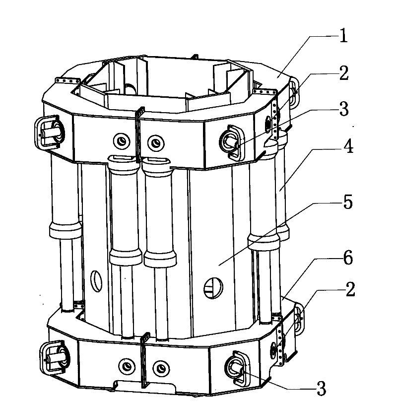
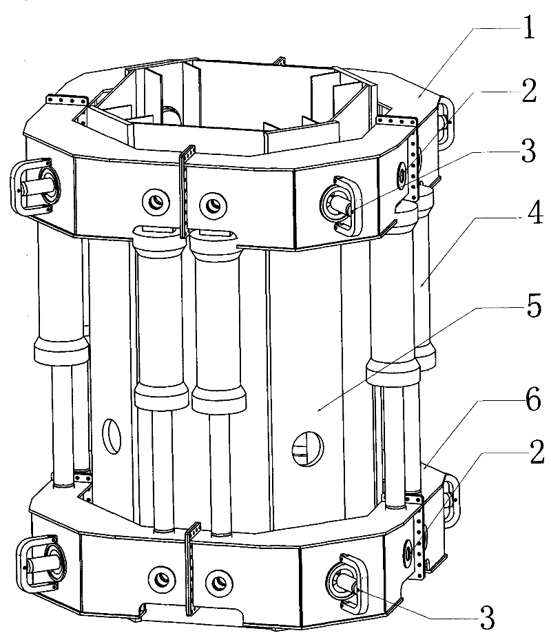
[0011] The present invention will be further described below in conjunction with all accompanying drawings. The preferred embodiment of the present invention is: a ring beam type hydraulic lifting device testing machine described in this embodiment, which includes an upper ring beam 1, a latch cylinder 2, a connecting Pin 3, lifting cylinder 4, testing machine leg 5, and lower ring beam 6, wherein the lifting cylinder 4 is located between the upper ring beam 1 and the lower ring beam 6, and is connected to the upper ring beam 1 and the lower ring beam respectively through the connecting pin 3 The beams 6 are connected; the bolt cylinder 2 is assembled in the upper ring beam 5 and the lower ring beam 9, and the pins matching the bolt cylinder 2 are arranged around the testing machine legs 5 in the upper ring beam 5 and the lower ring beam 9. hole, the testing machine leg 5 is connected with the upper ring beam 1 and the lower ring beam 6 through the bolt cylinder 2 . Among them...


PUM


Abstract

The invention provides a ring beam type hydraulic lifting device testing machine which comprises an upper ring beam, pin oil cylinders, connecting pins, a lifting oil cylinder, testing machine legs and a lower ring beam, wherein the lifting oil cylinder is positioned between the upper ring beam and the lower ring beam and respectively connected with the upper ring beam and the lower ring beam through the connecting pins; the pin oil cylinders are assembled in the upper ring beam and the lower ring beam; pin holes mated with the pin oil cylinders are formed around the testing machine legs in the upper ring beam and the lower ring beam; and the testing machine legs are connected with the upper ring beam and the lower ring beam through the pin oil cylinders. By the adoption of the technical scheme of the invention, the ring beam type hydraulic lifting device testing machine provided by the invention can completely simulate the actual working conditions after installation and effectively reduces the cost and risk after the actual installation.

Description

technical field [0001] The invention relates to the technical field of testing machines, in particular to a ring beam type hydraulic lifting device testing machine. Background technique [0002] At present, most companies or manufacturers generally use the method of directly putting the ring beam hydraulic lifting device into use. Few people conduct simulation tests on the ring beam hydraulic lifting device before installation, but this often leads to many problems. For example, the overall bearing capacity of the ring beam hydraulic lifting device after assembly cannot reach the expected effect or its stability is poor, which will greatly increase the cost and risk of the ring beam hydraulic lifting device after assembly. Therefore, there is a lack of equipment on the market that carries out a professional simulation test on the ring beam hydraulic lifting device before it is installed. Contents of the invention [0003] The purpose of the present invention is to overcom...

Claims


Application Information

Patent Timeline
IPC IPC(8): G01M99/00
Inventor 陆军
Owner 吴平平
Why Eureka
Try Eureka