Oil sampling tool for main transformer

A main transformer and oil sampling technology, applied in sampling devices and other directions, can solve the problems of pollution, easy to damage the site environment, easy to drip, etc., to achieve the effect of clean working environment, avoid oil sample pollution, and shorten working time.

Active Publication Date: 2011-10-19
STATE GRID CORP OF CHINA +1
View PDF3 Cites 10 Cited by
  • Summary
  • Abstract
  • Description
  • Claims
  • Application Information

AI Technical Summary

Problems solved by technology

Usually the on-load sampling valve of the main transformer is connected to the main transformer body through a long section of oil pipe, but the oil samples in this section of oil pipe are often seriously polluted and cannot truly reflect the oil samples of the main transformer body, so we take oil samples Usually it is necessary to drain the oil in the oil pipeline to get the oil sample of the oil body. Although the sampling valve of the main transformer is close to the main transformer body, the valve opening is larger than the diameter of the sampling bottle mouth, making the sampling Transformer oil is easy to drip around the sampling valve during oil sampling, polluting the environment and affecting the cleanliness of the substation
Defects of the current oil sampling: the current oil-chemical team usually takes oil samples directly by using plastic barrels to release the contaminated oil in this section of the oil pipeline. It is easy to drip and leak a lot of transformer oil on site, which is easy to damage the site environment. The pipeline is long and the oil drain valve port is large. Even if a lot of oil is put in, there is still a lot of contaminated oil remaining at the oil drain port, so that the oil sample taken out cannot truly reflect the quality of the transformer oil.

Method used


Image

  • Oil sampling tool for main transformer
  • Oil sampling tool for main transformer

Examples


Embodiment Construction

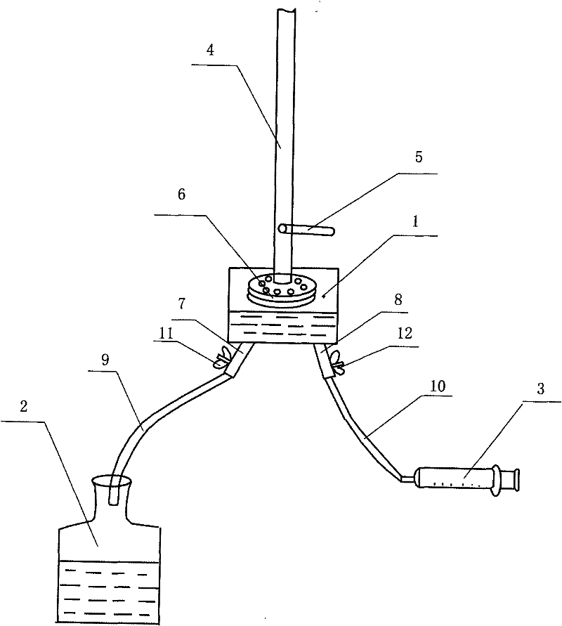
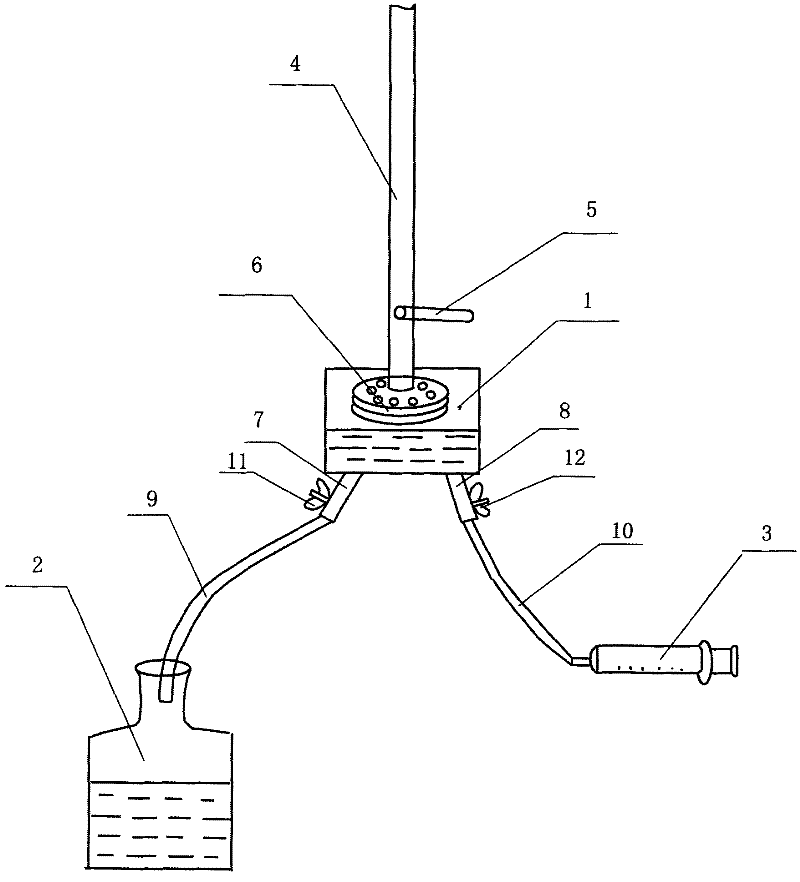
[0008] exist figure 1 Among them, the present invention is an oil sampling tool for a main transformer, a sampling bottle 1, a waste oil bottle 2 and a vacuum sampling device 3, the vacuum sampling device 3 is set as a vacuum syringe, and one end of the main transformer oil pipe 4 extends into the In the sampling bottle 1, an oil discharge valve 5 is provided on the main transformer oil pipe 4, and a sampling valve 6 is provided at the end where the main transformer oil pipe 4 extends into the sampling bottle 1. The sampling valve 6 is located in the sampling bottle 1, and the The bottom of the bottom is provided with oil leakage port I 7 and oil leakage port II 8 respectively, and oil leakage port I 7 and oil leakage port II 8 places are respectively provided with valve I 11 and valve II 12, on oil leakage port I 7 through pipeline I 9 communicates with the waste oil bottle 2, and communicates with the inlet of the vacuum sampling device 3 through the pipeline II 10 on the oi...


PUM


Abstract

The invention discloses an oil sampling tool for a main transformer. The oil sampling tool comprises a sampling bottle (1), a waste oil bottle (2) and vacuumizing sampling equipment (3). One end of a main transformer oil pipe (4) is extended into the sampling bottle (1). An oil drain valve (5) is arranged on the main transformer oil pipe (4). The end, extended into the sampling bottle (1), of themain transformer oil pipe (4) is provided with a sampling valve (6) which is positioned in the sampling bottle (1). The bottom of the sampling bottle (1) is provided with an oil leakage port I (7) and an oil leakage port II (8). The oil leakage port I (7) is communicated with the waste oil bottle (2) by a pipeline I (9). The oil leakage port II (8) is communicated with an inlet of the vacuumizingsampling equipment (3) by a pipeline II (10). The oil sampling tool not only can effectively protect an environment, but also can achieve good sampling effects and ensure high measurement accuracy.

Description

technical field [0001] The invention relates to an oil sampling tool for a main transformer. Background technique [0002] At present, due to the development of condition-based maintenance, the power outage cycle of equipment is extended, while the cycle of non-power outage test items such as oil testing is shortened. The chromatographic cycle of the main transformer oil of 220kV and above is 3 months, and the chromatographic cycle of 110kV and below is 6 months. The frequency of oil sampling for the main transformer is greatly increased. Usually the on-load sampling valve of the main transformer is connected to the main transformer body through a long section of oil pipe, but the oil samples of this oil pipe are often seriously polluted and cannot truly reflect the oil samples of the main transformer body, so we take oil samples Usually, it is necessary to drain the oil in the oil pipeline to get the oil sample of the oil body. Although the sampling valve of the main trans...

Claims


Application Information

Patent Timeline
Patent Type & Authority Applications(China)
IPC IPC(8): G01N1/14
Inventor 陶峰
Owner STATE GRID CORP OF CHINA
Why Eureka
Try Eureka