Photolithographic illumination device using mercury lamp light source

A technology for lighting devices and mercury lamps, which is applied in the field of semiconductors and can solve problems such as the inability to change the lighting mode

Inactive Publication Date: 2011-10-19
SHANGHAI MICRO ELECTRONICS EQUIP (GRP) CO LTD
View PDF6 Cites 10 Cited by
  • Summary
  • Abstract
  • Description
  • Claims
  • Application Information

AI Technical Summary

Problems solved by technology

This structure can well avoid energy loss and obtain changes in co

Method used


Image

  • Photolithographic illumination device using mercury lamp light source
  • Photolithographic illumination device using mercury lamp light source
  • Photolithographic illumination device using mercury lamp light source

Examples


Embodiment Construction

[0026] In the following, preferred embodiments according to the present invention will be described in detail with reference to the accompanying drawings.

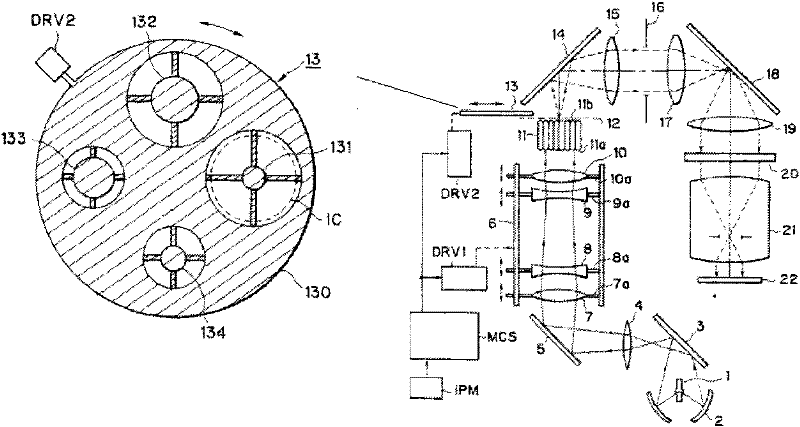
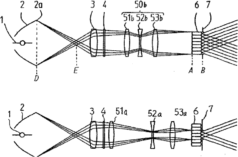
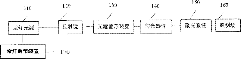
[0027] Such as image 3 As shown, the present invention discloses a lithography lighting device using a mercury lamp light source, comprising: a mercury lamp light source 110; a mercury lamp position adjusting device 170, which changes the light emitted by the mercury lamp light source 110 by moving the position of the mercury lamp Coherence factor; a reflective bowl 120, used to gather light energy of the mercury lamp; a pupil shaping device 130, to realize the conversion of illumination mode and the change of illumination coherence factor; a uniform light device 140, to obtain better illumination uniformity ; a focusing system 150 ; and an illumination field 160 . The reflective bowl 120 collects the light energy of the mercury lamp 110 and makes it enter the pupil shaping device 130 . The pupil shaping device 130 is u...


PUM


Abstract

The invention discloses a photolithographic illumination device using a mercury lamp light source. The photolithographic illumination device comprises the mercury lamp light source, a reflective bowl, a pupil reshaping device, a dodging device, a condensation system and a mercury lamp position adjusting device, wherein the reflective bowl is used for converging light energy of a mercury lamp; the pupil reshaping device is used for generating continuous and variable pupils and converting illumination modes; the dodging device is used for acquiring better illumination uniformity; and the mercury lamp position adjusting device is used for changing coherence factors of rays emitted by the mercury lamp light source by moving the position of the mercury lamp to acquire a required illumination field. Through the illumination device provided by the invention, the illumination modes and the illumination coherence factors can be simply converted by using fewer elements, and the elements do not need to be changed.

Description

technical field [0001] The invention relates to the field of semiconductors, in particular to a photolithography illuminating device using a mercury lamp light source. Background technique [0002] Adopt the optical system of high-pressure mercury lamp illumination in the existing lithography method, mainly expose to g (436nm) h (405nm) i (365nm) three lines, obtain certain photoresist pattern on the silicon chip that is coated with photoresist, and then The same photoresist pattern is obtained on the silicon wafer through etching and other steps. [0003] According to different exposure requirements, different exposure fields of view, numerical apertures or coherence factors are sometimes required on the silicon wafer. Moreover, it is necessary to be able to produce the most uniform intensity distribution on the lighting surface of the lighting system, and to be able to set various lighting modes of the lighting system, which helps to improve the quality of exposure and ob...

Claims


Application Information

Patent Timeline
IPC IPC(8): G03F7/20
Inventor 韩雨青
Owner SHANGHAI MICRO ELECTRONICS EQUIP (GRP) CO LTD
Why Eureka
Try Eureka