Tool holder

A tool holder and tool technology, which is used in the manufacture of tools, mechanical equipment, tool holders, etc., can solve the problems of limiting the possibility of using the tool holder and the total length of the axial direction.

Inactive Publication Date: 2011-10-26
MAPAL FABRIK FUER PRAEZISIONSWERKZEUGE (DE)
View PDF6 Cites 10 Cited by
  • Summary
  • Abstract
  • Description
  • Claims
  • Application Information

AI Technical Summary

Problems solved by technology

In many cases, the overall axial length (i.e. the length measured in the direction of the central axis of the tool holder) is large, which limits the use possibilities of such tool holders

Method used


Image

  • Tool holder
  • Tool holder
  • Tool holder

Examples


Embodiment Construction

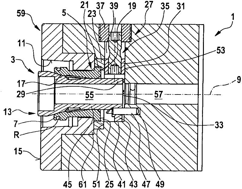
[0029] figure 1 A tool holder 1 with a quill holder 3 is shown. The hollow shaft taper shank clamp 3 includes a clamping device 5 , and the clamping device 5 includes at least one clamping chuck 7 . In order to be able to introduce the clamping force as uniformly as possible on the hollow shaft of the tool (not shown) that should be clamped and fixed in the tool holder 1, the clamping device usually has a plurality of The clamping jaws 7 are arranged at the same distance from one another. Said clamping chuck 7 engages in a hollow shaft of a tool (not shown) and cooperates with a clamping surface provided on the inner side of the hollow shaft, said clamping surface being formed so as to remove substantially radially from the clamping The force exerted by the clamping chuck 7 - that is to say the force acting perpendicularly to the central axis 9 - is resolved into a force component which acts radially outward and presses the hollow shaft taper against the receiving surface of...


PUM


Abstract

The invention relates to a tool holder comprising: a hollow-shaft taper chucking device having a center axis (9), a chucking unit (7) having at least one collet chuck (7), which can be inserted into the hollow shaft of a tool, a tension rod (13) which can be moved in the direction of the center axis (9) and cooperates with the at least one collet chuck (7) such that in a first function position of the tension rod (13), the at least one collet chuck (7) is forced radially outward into a chucking position, and in a second function position of the tension rod (13), it can bend radially inward in the direction of the center axis (9) and further comprising an operating unit (27) which cooperates with the tension rod (13). According to the invention, the operating unit (27) has an operating element (31) that can be moved at an angle of preferably 90 DEG to the center axis (9) and comprises at least one operating part (33), the tension rod (13) has at least one engagement part (99), and the operating part (33) and the engagement part (99) form a wedge gear, so that the operating part (33) induces an axial displacement of the tension rod (13) with a radial displacement of the operating element (31).

Description

technical field [0001] The invention relates to a tool holder having the features of claim 1 . Background technique [0002] Tool holders with hollow shaft taper holders are known, wherein the characteristics of the hollow shaft taper are specified by DIN and ISO. [0003] This type of tool holder is used to receive tools with a hollow shaft taper, as well as adapters, intermediate parts, etc., and connect them firmly to the bracket. The tool clamped in this way is used to machine the workpiece. For example, a turning tool is used to remove chips from a rotating workpiece. In this case, the tool remains stationary, that is to say the tool does not rotate, for example, about the center axis of the tool holder. However, a tool holder of this type can also receive a tool so that the tool can be used for drilling, grinding or milling, the tool usually being rotated. In many cases, the overall axial length, ie the length measured in the direction of the center axis of the too...

Claims


Application Information

Patent Timeline
Patent Type & Authority Applications(China)
IPC IPC(8): B23B31/26
CPCB23B29/046B23B31/261B23B2250/12Y10T82/2587Y10T409/304032Y10T409/30952Y10T82/2589Y10T279/17411
Inventor 约瑟夫·瑞恩奥尔
Owner MAPAL FABRIK FUER PRAEZISIONSWERKZEUGE (DE)
Why Eureka
Try Eureka