
Central oil distributor for rotary machine tool

A technology of oil separator and rotary type, which is applied in the direction of metal processing machinery parts, clamping, support, etc., can solve the problems of frequent faults of machine tools, unguaranteed assembly accuracy and effect, and complicated assembly, so as to improve the rotary processing accuracy and The effect of overall machine tool performance, improvement of part processing manufacturability, and ease of operation and maintenance

Inactive Publication Date: 2011-11-02
北京北方红旗精密机械制造有限公司
View PDF5 Cites 8 Cited by
  • Summary
  • Abstract
  • Description
  • Claims
  • Application Information

AI Technical Summary

Problems solved by technology

If the design of the customary center oil separator structure is followed, the current domestic machining capabilities and methods will inevitably have processing difficulties, unguaranteed machining accuracy, high processing costs, complicated assembly, unguaranteed assembly accuracy and effects, and leakage. , frequent machine failures, inconvenient maintenance and many other problems

Method used


Image

  • Central oil distributor for rotary machine tool
  • Central oil distributor for rotary machine tool
  • Central oil distributor for rotary machine tool

Examples


Embodiment Construction

[0033] The principles and features of the present invention are described below in conjunction with the accompanying drawings, and the examples given are only used to explain the present invention, and are not intended to limit the scope of the present invention.

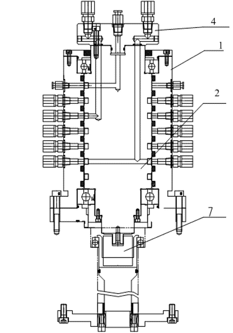
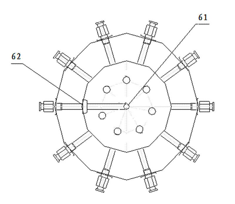
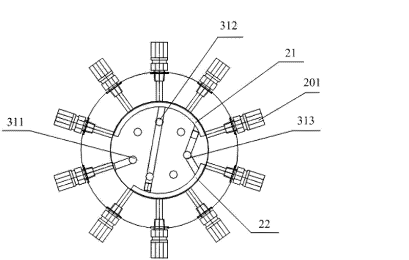
[0034] Such as figure 1 As shown, a central oil separator for a rotary machine tool includes an oil separator jacket 1 and a mandrel 2 inside the oil separator jacket. The mandrel 2 is provided with an air blowing cleaning mechanism, an oil cylinder clamp tightening mechanism, cylinder release mechanism, auxiliary support mechanism, taper pin locking mechanism, taper pin release mechanism and oil leakage prevention mechanism, the top of the mandrel 2 is provided with an oil circuit integration mechanism 4, and the oil circuit integration The mechanism 4 is provided with a plurality of input ports, and the input ports are connected with corresponding oil inlets or air inlets on the upper end surface of the mandrel 2...


PUM


Abstract

The invention relates to a central oil distributor for a rotary machine tool, comprising an oil distributor casing and a mandrel arranged in the oil distributor casing, wherein a blowing and cleaning mechanism, an oil cylinder clamping mechanism, an oil cylinder loosening mechanism, an auxiliary support mechanism, a tapered pin locking mechanism and a tapered pin loosening mechanism are arranged on the mandrel from top to bottom. The central oil distributor disclosed by the invention has the beneficial effects of realizing various functional requirements of the machine tool, reducing the costas much as possible, improving the machining manufacturability of parts, improving the precision of the parts and being convenient for operation and maintenance.

Description

technical field [0001] The invention relates to a central oil separator for a rotary machine tool. Background technique [0002] The central oil separator is an important functional part of the rotary multi-station combined machine tool. Through this device, the automatic or manual clamping and loosening of the machine tool fixture to the workpiece processed by the machine tool is realized. Usually, it is composed of gas, hydraulic oil, coolant access adapter, mandrel 4, jacket 5, screws, bearings, sealing ring 2, rotary table 7, and connection 8. Generally speaking, its main structure is as Figure 9 as shown, Figure 10 The middle pipe joint 6 is connected to the oil inlet 1 of the oil cylinder in the fixture, Figure 11 The middle pipe joint is connected to the oil discharge port of the oil cylinder in the fixture. Its working principle: the rotary table 7 drives the outer casing 5 to rotate, the mandrel 4 and the connecting body 8 are fixed and do not rotate relative ...

Claims


Application Information

Patent Timeline
IPC IPC(8): B23Q3/06
Inventor 郭亮温京华刘书斌
Owner 北京北方红旗精密机械制造有限公司
Learn More