Compact single-suction centrifugal fan

A centrifugal fan, single-suction technology, applied in the direction of mechanical equipment, non-variable pumps, machines/engines, etc., can solve the problem of excessive axial size of the casing, increased bending stress of blades, and difficulty in meeting the requirements of high-quality carbon steel and other issues to achieve the effect of improving operating efficiency, improving flow field and reducing flow resistance

Inactive Publication Date: 2013-07-03
SHANGHAI JIAO TONG UNIV
View PDF4 Cites 0 Cited by
  • Summary
  • Abstract
  • Description
  • Claims
  • Application Information

AI Technical Summary

Problems solved by technology

[0006] 2. After determining the diameter of the impeller according to the air volume required by the system, the calculated width of the impeller should be 80% larger than that of the usual impeller, which will increase the bending stress of the blade to 3.24 times, making it difficult for high-quality carbon steel to meet the requirements, and the casing The axial dimension will be seriously exceeded

Method used


Image

  • Compact single-suction centrifugal fan
  • Compact single-suction centrifugal fan
  • Compact single-suction centrifugal fan

Examples


Embodiment Construction

[0022] The technical solutions of the present invention will be further described below in conjunction with the accompanying drawings and embodiments.

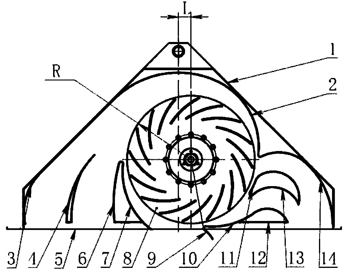
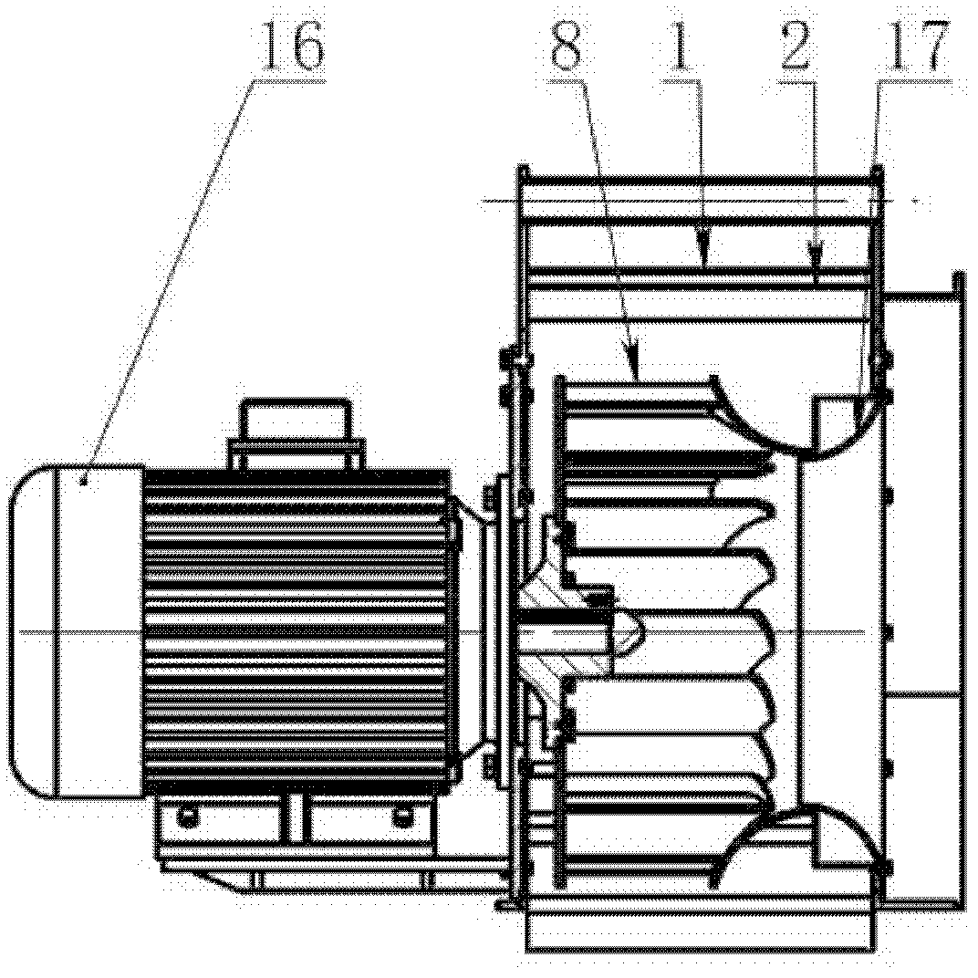
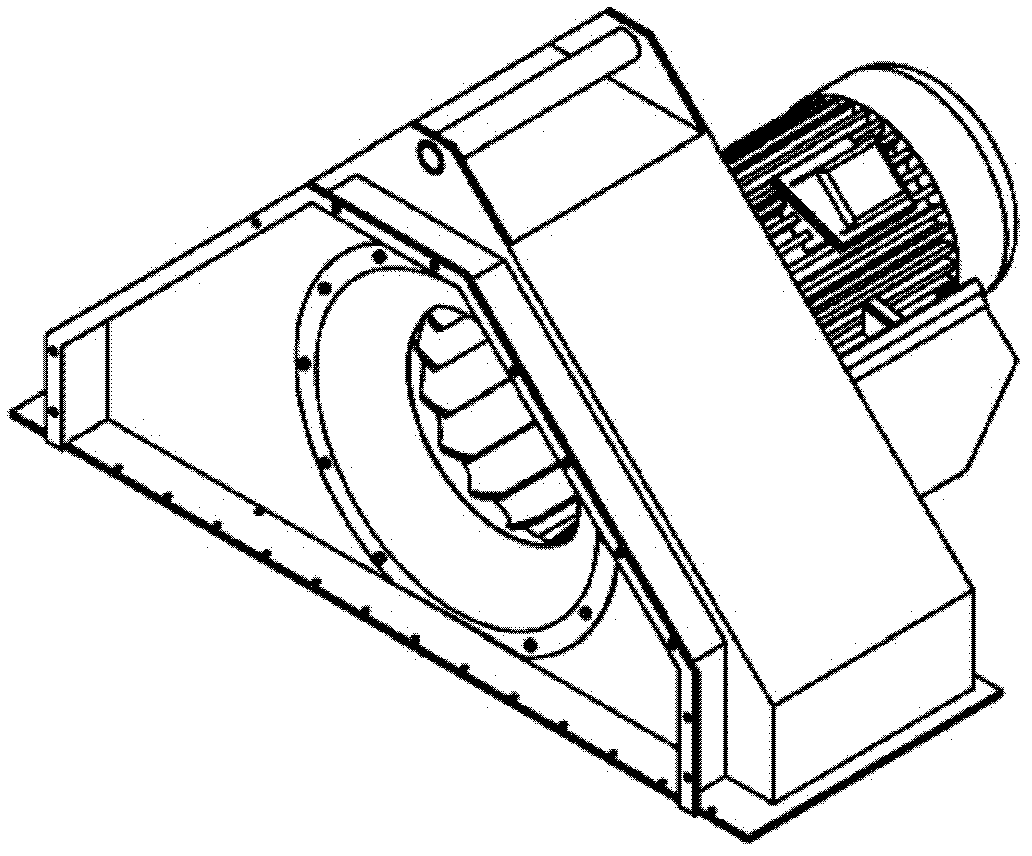
[0023] figure 1 It is a structural schematic diagram of an embodiment of the centrifugal fan of the present invention. like figure 1 As shown, the casing of the ventilator can only be designed as a triangle according to the site conditions, and a centrifugal impeller 8 is built in the triangular cavity 1, and the vertical centerline of the impeller 8 is offset to the right. The distance between the plane of symmetry) is L, and the value of L is 0.18-0.22R, where R is the radius of the impeller.

[0024] Around the rotation center of the impeller 8, four sections of half-volutes with different lengths are distributed sequentially, and the profiles of the four sections of half-volutes with different lengths are all logarithmic spirals. Among them, the starting point of the volute tongue of the first half volute 2 starts from ...


PUM


Abstract

The invention relates to a compact single-suction centrifugal fan. The fan is structurally characterized in that a single-suction centrifugal impeller is adopted, and a half volute is additionally provided with a special guide vane; the impeller is placed in a triangular cavity of a narrow size; four sections of half volutes of different lengths are successively distributed around the rotation center of the impeller; the molded lines of the half volutes are all logarithm spiral lines; according to the function requirements of the fan, a plurality of special guide vanes are additionally arranged on the air exhaust end of the impeller; the shape, relative position and structure size of the special guide vanes are determined according to the flow rate evenness, small resistance loss and steering divergent characteristic organization airflow in a runner; the flow of each air outlet is distributed by the guide vane; the flow is effectively controlled in the triangular cavity space; and thesteering flow guidance and speed can be subjected to stable gradual change to reduce flow separation and isolation, thereby effectively lowering the flow resistance. The compact single-suction centrifugal fan is especially suitable for occasions with narrow space and harsh mounting conditions.

Description

technical field [0001] The invention relates to a compact single-suction centrifugal fan, in particular to a compact single-suction centrifugal fan suitable for harsh installation conditions and narrow installation space such as a triangular cavity. It belongs to the technical field of fluid engineering. Background technique [0002] Before the design of the domestic super large motor structure is finalized, it is required to complete the design verification of the cooling system as the basis for the motor design, and the fan is the key equipment. At present, the widely used centrifugal fan is a centrifugal fan with a full volute, and the size of the fan casing is relatively large. In order to ensure the high operating efficiency of the fan and the uniformity of the flow field at the inlet and outlet of the fan, it is required to have enough room for installation. In actual engineering, it is necessary to install fans in certain narrow, triangular spaces, such as high-speed...

Claims


Application Information

Patent Timeline
IPC IPC(8): F04D29/28F04D29/42
Inventor 任世瑶任勇罗建平董新祥
Owner SHANGHAI JIAO TONG UNIV
Why Eureka
Try Eureka