
Robot system

A robot system and robot arm technology, applied in the field of robot systems, can solve problems such as the inability to prevent abnormal movements of robots

Active Publication Date: 2011-11-09
FANUC LTD
View PDF6 Cites 27 Cited by
  • Summary
  • Abstract
  • Description
  • Claims
  • Application Information

AI Technical Summary

Problems solved by technology

However, in the device described in JP6-91587A, when the sensor for detecting acceleration and speed fails, it is impossible to prevent the abnormal operation of the robot.

Method used


Image

  • Robot system
  • Robot system
  • Robot system

Examples


Embodiment Construction

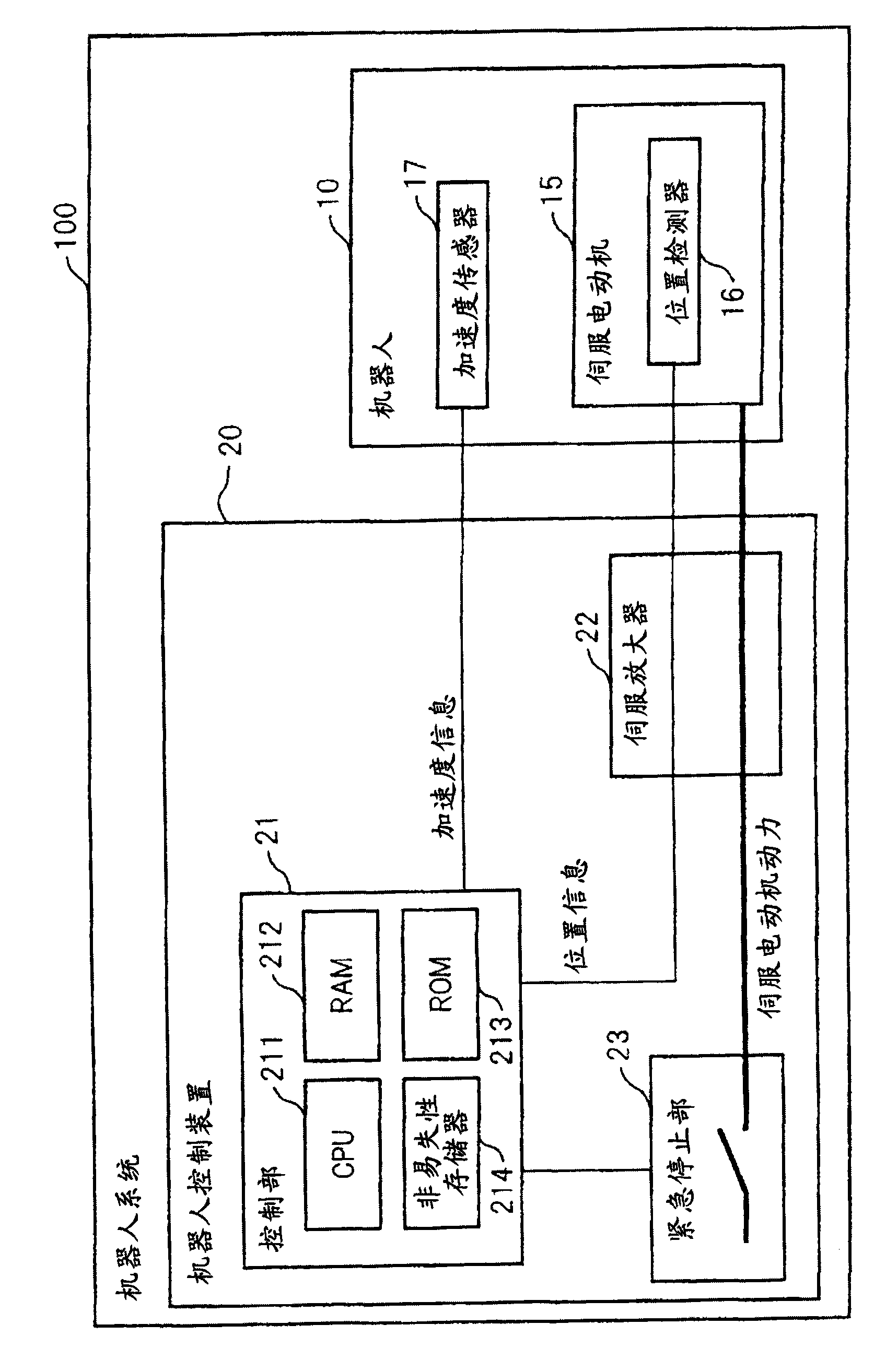
[0008] Refer to the following Figure 1 ~ Figure 3 Embodiments of the present invention will be described. figure 1 The configuration of the robot system 100 according to the embodiment of the present invention is shown. This robot system 100 includes an articulated industrial robot 10 and a robot controller 20 that controls the robot 10 .

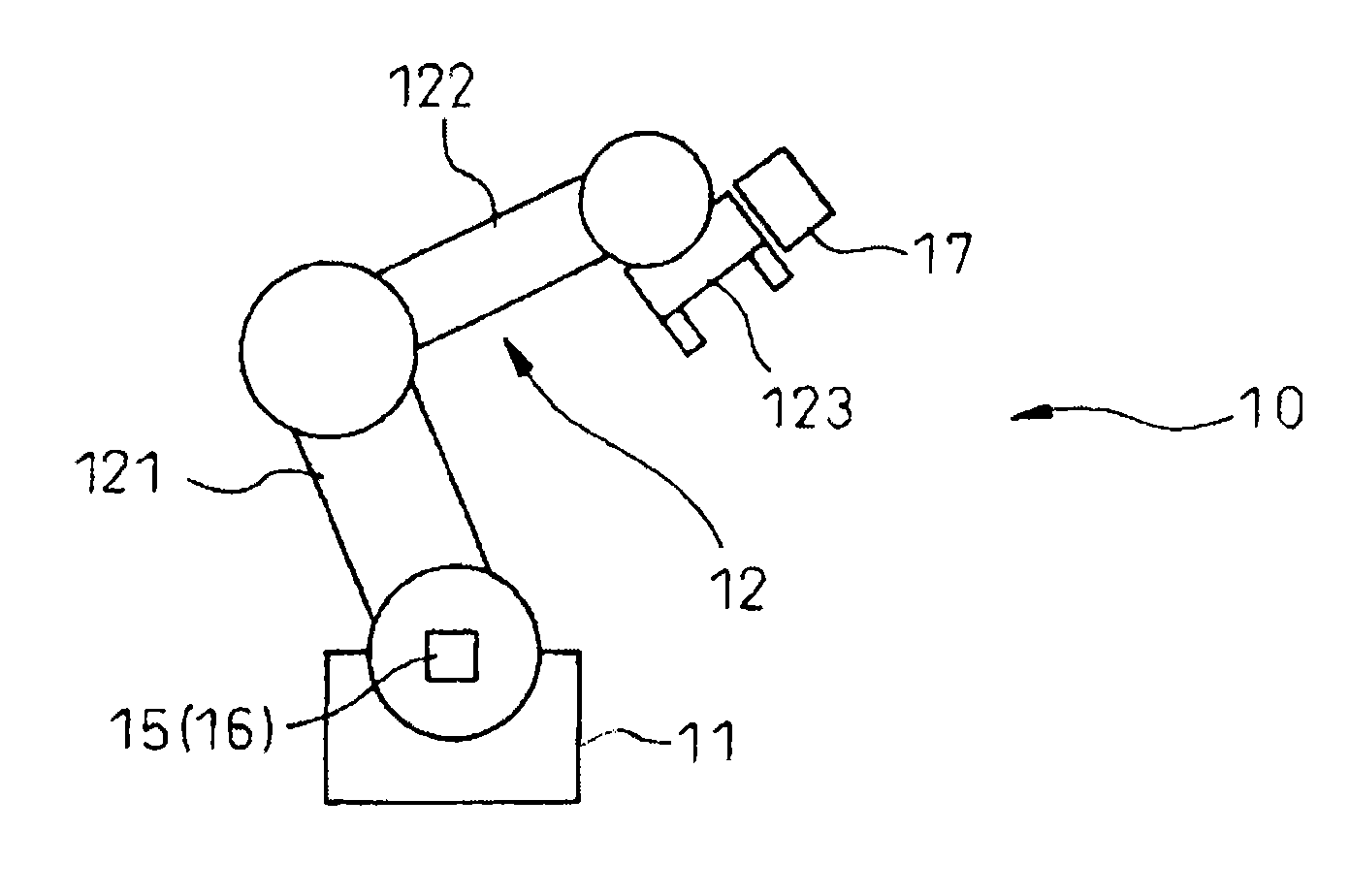
[0009] figure 2 The configuration of the commercial robot 10 is schematically shown. The robot 10 is generally a 6-axis vertical multi-joint robot, which includes a base 11 fixed on the ground, and a robot arm 12 rotatably connected to the base 11 . The robot arm 12 has a lower arm 121 , an upper arm 122 rotatably connected to a front end of the lower arm 121 , and a working device 123 (for example, a welding torch) rotatably attached to a front end of the upper arm 122 .

[0010] The robot 10 incorporates a plurality of (only one is shown for convenience) robot-driving servo motors 15 . An encoder (referred to as a position detector...


PUM


Abstract

A robot system including a robot arm driven by a servo motor; and a robot controller controlling an operation of the robot arm. The robot system further comprises a first detection section detecting a rotation amount of the servo motor; a second detection section attached to a tip portion of the robot arm, and detecting a velocity or acceleration of the tip portion of the robot arm; a computationsection computing the velocity or acceleration of the tip portion of the robot arm based on values detected by the first detection section, and computing a deviation between this computed velocity oracceleration and the velocity or acceleration detected by the second detection section; and an emergency stop section for bringing the servo motor to an emergency stop when a magnitude of the deviation computed by the computation section is greater than a reference value.

Description

technical field [0001] The present invention relates to a robot system for detecting abnormal motion of an industrial robot. Background technique [0002] Conventionally, there is known a device that detects the acceleration and velocity of the front end of a robot arm, and determines that the robot is in an abnormal state when either of the acceleration and velocity becomes greater than a predetermined value, and causes the robot to stop in an emergency. This device is described in JP-A-6-91587 (JP6-91587A). However, in the device described in JP6-91587A, when a sensor for detecting acceleration and velocity fails, abnormal operation of the robot cannot be prevented. Contents of the invention [0003] According to one aspect of the present invention, the robot system includes a servo motor, a robot arm driven by the servo motor, a robot controller for controlling the movement of the robot arm, a first detection unit for detecting the rotation amount of the servo motor, a...

Claims


Application Information

Patent Timeline
Patent Type & Authority Applications(China)
IPC IPC(8): B25J19/06
CPCG05B2219/40549G05B2219/37388G05B2219/42329B25J9/1674
Inventor 二瓶亮加藤哲朗荒牧武亮山本知之
Owner FANUC LTD
Learn More