Rotating motor, elevator tractor with same, and elevator

A technology for rotating electrical machines and traction machines, applied in electrical components, electromechanical devices, electrical components, etc., can solve the problems of reduced motor performance, reduced heat dissipation area, magnet demagnetization, etc., and achieves the effect of improving cooling performance and reliability.

Active Publication Date: 2017-03-08
HITACHI LTD
View PDF4 Cites 12 Cited by
  • Summary
  • Abstract
  • Description
  • Claims
  • Application Information

AI Technical Summary

Problems solved by technology

However, if the motor is thinned and miniaturized, the heat dissipation area will also be reduced, so the temperature of the excitation coil and the temperature of the magnet will rise excessively, causing problems such as insulation breakdown of the excitation coil and demagnetization of the magnet, and the performance of the motor may be affected. will reduce

Method used


Image

  • Rotating motor, elevator tractor with same, and elevator
  • Rotating motor, elevator tractor with same, and elevator
  • Rotating motor, elevator tractor with same, and elevator

Examples


Embodiment 1

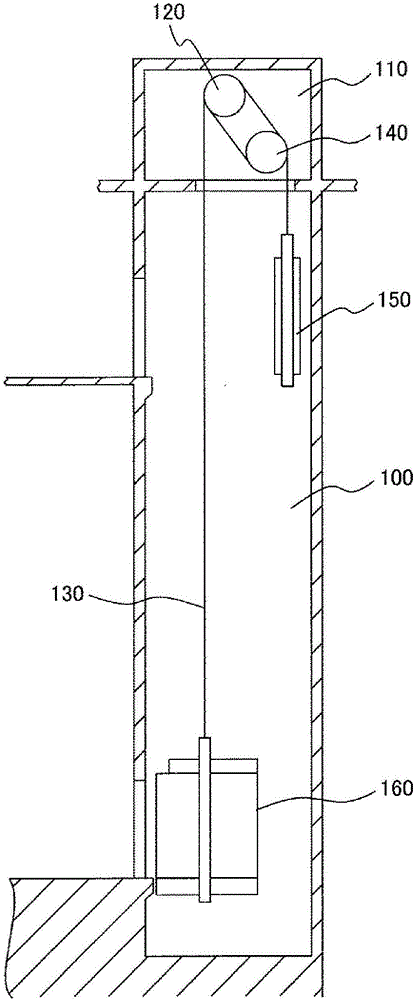
[0040] figure 1 An outline of the overall structure of the elevator according to Embodiment 1 of the present invention is shown.

[0041] Such as figure 1 As shown, a machine room 110 is provided on the top of a hoistway 100 installed in a building, and a traction machine 120 is placed in the machine room 110 and fixed on the floor of the machine room by a fixing mechanism. The traction machine 120 has a plurality of sheaves for suspending a plurality of main ropes 130 . One end of the main rope 130 extending from the sheave is connected to the upper end of the counterweight 150 via the guide pulley 140 , and the other end is connected to the upper end of the car 160 . The car 160 and the counterweight 150 are hoisted in the hoistway 100 by the main rope 130 wound on the sheave.

[0042] When the traction machine 120 works to rotate the sheave, the main rope 130 is driven along the rotation direction of the sheave due to the friction between the main rope 130 and the sheave...

Embodiment 2

[0080] Next, use Figure 11 and Figure 12 Example 2 of the present invention will be described. The differences from Embodiment 1 will be mainly described below.

[0081] Figure 11 It is an external perspective view of the traction machine of Example 2. and Figure 5 Likewise, a state in which the stator 31 and the rotor 30 are spaced apart from each other in the axial direction is shown. Figure 12 express Figure 11 A truncated section along A-A in the middle.

[0082] This embodiment 2 is different from embodiment 1 in that no opening is provided on the end frame 33 ( Figure 5 35A, 35B). That is, the partial space in which the blower vane 41 is located is completely closed on the side opposite to the connection portion side of the rotor 30 connected to the sheave 13 . Therefore, in addition to the partial space where the stator core including the field coil 37 and the permanent magnet 40 are located is substantially sealed, the partial space where the blower van...

Embodiment 3

[0088] Next, use Figure 13 and Figure 14 Embodiment 3 of the present invention will be described. The differences from Embodiment 1 will be mainly described below.

[0089] Figure 13 It is a perspective view showing the appearance and axial cross-section of the hoisting machine according to the third embodiment. and Figure 5 Likewise, a state in which the stator 31 and the rotor 30 are spaced apart from each other in the axial direction is shown. in, Figure 13 together expressed Figure 7 and Figure 9 Airflows AF3 and AF4 are shown in respectively. and Figure 14 only means Figure 13 Axial section in .

[0090] The present embodiment 3 is different from the embodiment 1 in that the connection portion 47 between the frame 39 of the rotor 30 and the sheave 13 protrudes toward the stator core support portion 32a, and is connected to the stator core support portion 32a on the inner peripheral side of the stator core support portion 32a. Free ends on the opposite...


PUM


Abstract

The invention provides a rotating motor which can prevent dust entering and improves cooling performance even on the condition that small size or small thickness is realized, an elevator tractor with same, and an elevator. The rotating motor comprises a stator (31) and a rotor (30), wherein the stator comprises a stator core (34), an exciting coil (37) which is arranged on the stator core, and a first supporting member (32,33) which supports the stator core and the exciting coil. The rotor comprises a magnetic pole part (40) and a second supporting member (39) which supports the magnetic pole part. The stator core and the exciting coil are arranged in a partial space which is closed by the first supporting member and the second supporting member in the space that are defined by the first supporting member and the second supporting member. The rotating motor further comprises a blasting blade (41) which is provided with a plurality of blades and rotates together with rotation of the rotor. The blasting blade is arranged in the rest partial space and is arranged at the inner circumferential side of the stator core and the exciting coil.

Description

technical field [0001] The present invention relates to a rotating electrical machine, an elevator traction machine using the rotating electrical machine, and an elevator. Background technique [0002] In recent years, for the purpose of restricting installation space, reducing structural materials, reducing electric power, etc., there is a demand for thinning and downsizing of electric motors in elevator traction machines. However, if the motor is thinned and miniaturized, the heat dissipation area will also be reduced, so the temperature of the excitation coil and the temperature of the magnet will rise excessively, causing problems such as insulation breakdown of the excitation coil and demagnetization of the magnet, and the performance of the motor may be affected. will decrease. In contrast, conventional technology described in Patent Document 1 is known as a technology for obtaining a cooling effect in the hoisting machine for elevators. [0003] In this prior art, a...

Claims


Application Information

Patent Timeline
Patent Type & Authority Applications(China)
IPC IPC(8): H02K5/10H02K9/06
CPCH02K5/10H02K9/06
Inventor 佐野健太郎西原淳夫尾方尚文
Owner HITACHI LTD
Why Eureka
Try Eureka