Sewing machine

A technology of sewing machine and driving mechanism, which is applied in the direction of sewing machine components, sewing equipment, mechanism of cutting thread in sewing machine, etc., to achieve the effect of simple structure

Inactive Publication Date: 2011-11-09
BROTHER KOGYO KK
View PDF7 Cites 10 Cited by
  • Summary
  • Abstract
  • Description
  • Claims
  • Application Information

AI Technical Summary

Problems solved by technology

The reason for this is that the pusher thread wiper drive motor is a large component, and there is no space to arrange it in the column part together with the solenoid actuator

Method used


Image

  • Sewing machine
  • Sewing machine
  • Sewing machine

Examples


Embodiment Construction

[0043] Embodiments of the present invention will be described below with reference to the accompanying drawings.

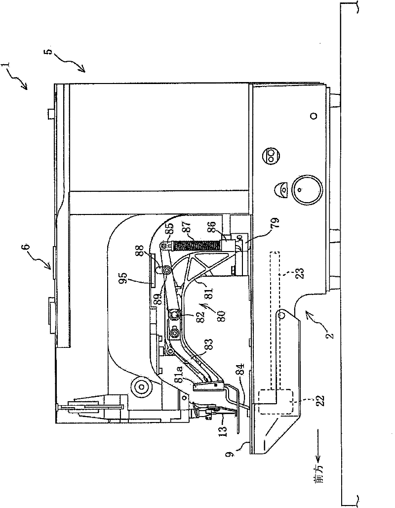
[0044] Such as figure 1 As shown, the sewing machine 1 includes a base portion 2 , a column portion 5 , and an arm portion 6 . The base portion 2 is long in the front-rear direction. The column portion 5 stands upright from the rear end portion of the base portion 2 . The arm portion 6 extends forward from the upper end portion of the column portion 5 so as to face the base portion 2 .

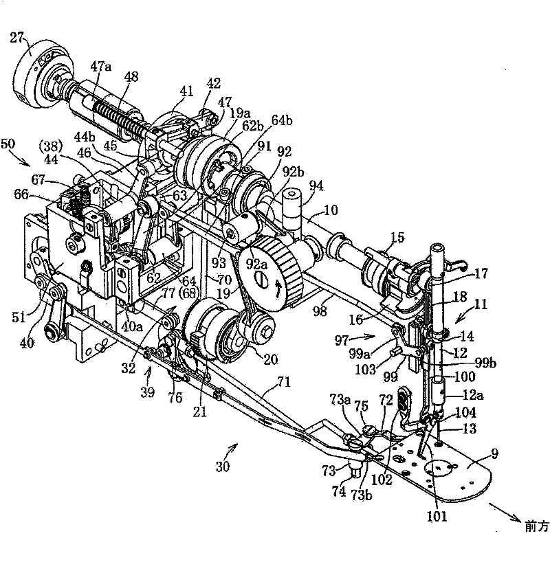
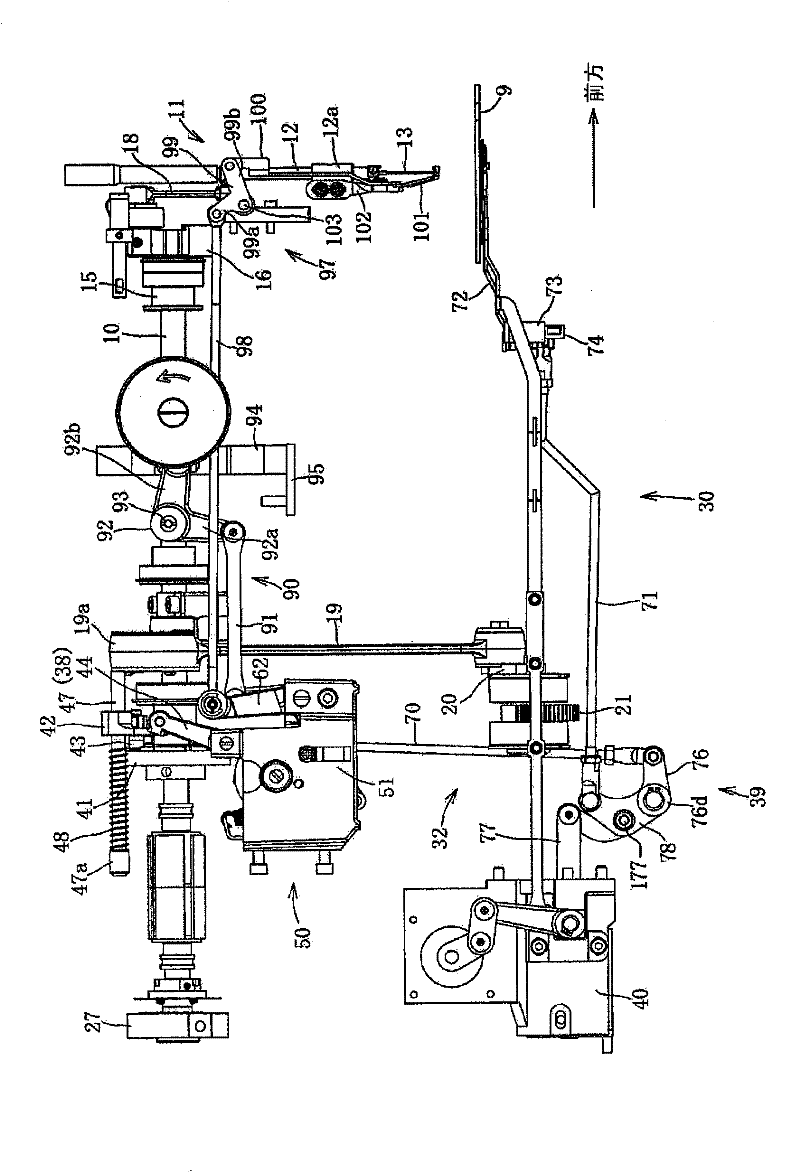
[0045] Such as figure 1 , figure 2 As shown, the sewing machine main shaft 10 is disposed in the front-rear direction inside the column portion 5 and the arm portion 6 . A sewing machine motor 27 (only a part is shown) is provided at the rear end of the sewing machine main shaft 10 . The sewing machine motor 27 drives the sewing machine spindle 10 . At the front of the sewing machine main shaft 10, a main shaft supporting member 15 is provided. The spindle supporting memb...


PUM


Abstract

The invention provides a sewing machine, comprising a thread cutting mechanism. The thread cutting mechanism is provided with a thread cutting cam and a roller component. The roller component clamps with the thread cutting cam plate. The thread cutting cam plate is fixed at the mains haft of the sewing machine. The roller component is disposed at a driving rod, the driving rod moves between a clamping position and a preventing position, at the clamping position, the roller member clamps with the thread cutting cam plate, at the preventing position, the roller component deviates from the thread cutting cam plate. The driving rod moves between the clamping position and the preventing under the effect of an oscillating force generating mechanism. The driving rod oscillates at the clamping position via movement of the roller member. Oscillation of the driving rod is transmitted to a moveable knife via a thread cutting collecting rod mechanism. The moveable knife is in a reciprocating rotation, and stopped when approaching to a fixed knife. The oscillating force generating mechanism and a cloth pressing member upper-lower driving mechanism driving a cloth-pressing piece are driving by a driving pulse motor. The driving pulse motor, the cloth pressing member upper-lower driving mechanism, and the oscillating generating mechanism are configured in a vertical column part of the sewingmachine. The main shaft of the sewing machine is driven by a motor of the sewing machine.

Description

technical field [0001] The invention relates to a miniaturized sewing machine including a cloth pressing mechanism and a thread cutting mechanism. Background technique [0002] A sewing machine for forming tack stitches includes a cloth pressing mechanism and a thread cutting mechanism. The cloth pressing part moves up and down under the action of the cloth pressing mechanism to press the processed cloth. The thread cutting mechanism includes a sewing machine spindle, a thread cutting cam, a lever, and a solenoid actuator. The thread cutting cam is fixed on the main shaft of the sewing machine. The rod has an engaging portion. When the solenoid actuator is actuated, the rod moves. The engaging part engages with the thread cutting cam by movement of the lever. The thread trimming mechanism cuts the upper and lower threads at the end of sewing. [0003] A thread cutting device for a sewing machine described in Japanese Laid-Open Patent Publication No. 61020 of 2009 inclu...

Claims


Application Information

Patent Timeline
Patent Type & Authority Applications(China)
IPC IPC(8): D05B65/00D05B29/00
Inventor 山田泰史中野元就
Owner BROTHER KOGYO KK
Why Eureka
Try Eureka