
Method of multiple injection timing control

A technology of injection timing and fuel injection timing, applied in the direction of fuel injection control, electrical control, engine control, etc.

Active Publication Date: 2011-11-09
GM GLOBAL TECH OPERATIONS LLC
View PDF6 Cites 6 Cited by
  • Summary
  • Abstract
  • Description
  • Claims
  • Application Information

AI Technical Summary

Problems solved by technology

However, such methods are only as accurate as the calibration values ​​allow

Method used


Image

  • Method of multiple injection timing control
  • Method of multiple injection timing control
  • Method of multiple injection timing control

Examples


Embodiment Construction

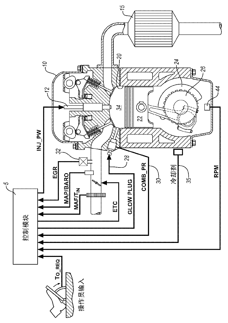
[0123] Referring now to the drawings, in which certain exemplary embodiments are shown for purposes of illustration only and not for limitation, figure 1 is a schematic diagram depicting an exemplary internal combustion engine 10, control module 5, and exhaust aftertreatment system 15 constructed in accordance with an embodiment of the present invention. Exemplary engines include multi-cylinder, direct injection, compression ignition internal combustion engines having reciprocating pistons 22 connected to crankshaft 24 and movable within cylinders 20 defining variable volume combustion chambers 34 . Crankshaft 24 is operatively connected to the vehicle transmission and driveline in response to an operator torque request (T O _ REQ ) to transmit traction torque to it. The engine preferably operates on a four-stroke wherein each engine combustion cycle includes a 720 degree angular displacement of the crankshaft 24 divided into four 180 degree phases describing the reciprocati...


PUM


Abstract

The invention relates to a method of multiple injection timing control. A method for adjusting fuel injection timing in an internal combustion engine including a cylinder and configured to operate multiple fuel injections in the cylinder per combustion cycle includes monitoring in-cylinder pressure through a first combustion cycle, determining actual combustion phasing metrics based upon the in-cylinder pressure, monitoring a baseline fuel injection timing comprising a first injection timing and a second injection timing, providing expected combustion phasing metrics based upon the baseline fuel injection timing, comparing the actual combustion phasing metrics to the expected combustion phasing metrics, and adjusting the baseline fuel injection timing in a second combustion cycle based upon the comparing.

Description

technical field [0001] The present invention relates to the operation and control of internal combustion engines. Background technique [0002] The statements in this section merely provide background information related to the present disclosure and may not constitute prior art. [0003] Injection in different portions of the combustion cycle has different effects on the resulting combustion cycle, including effects on engine work output, emissions, and combustion stability. The fuel injection timing for each of the multiple fuel injections may be controlled, adjusted, or corrected, for example, by monitoring engine load and using calibration values ​​to determine the proper timing of each pulse in the multiple injection schedule. However, such methods are only as accurate as the calibration values ​​allow. Furthermore, it will be appreciated that such methods are reactive and include a time lag, controlling engine operation for a period of time after the measured input. ...

Claims


Application Information

Patent Timeline
IPC IPC(8): F02D41/40
CPCF02D41/402F02D35/028Y02T10/44F02D35/023Y02T10/40
Inventor I.哈斯卡拉Y-Y.王C-B.M.关F.A.马特库纳斯O.H.达奇
Owner GM GLOBAL TECH OPERATIONS LLC
Features
  • Generate Ideas
  • Intellectual Property
  • Life Sciences
  • Materials
  • Tech Scout
  • Unparalleled Data Quality
  • Higher Quality Content
  • 60% Fewer Hallucinations
Learn More