Fuel distribution device for a motor vehicle and method for producing a fuel distribution device

A fuel distribution and motor vehicle technology, which is applied to fuel injection devices, machines/engines, low-pressure fuel injection, etc., can solve the problems of complexity and expensive manufacturing of fuel distribution devices, and achieve the effect of high manufacturing precision

Inactive Publication Date: 2014-12-10
AUDI AG
View PDF7 Cites 0 Cited by
  • Summary
  • Abstract
  • Description
  • Claims
  • Application Information

AI Technical Summary

Problems solved by technology

[0005] Such fuel distribution devices are especially expensive / complicated to manufacture

Method used


Image

  • Fuel distribution device for a motor vehicle and method for producing a fuel distribution device
  • Fuel distribution device for a motor vehicle and method for producing a fuel distribution device

Examples


Embodiment Construction

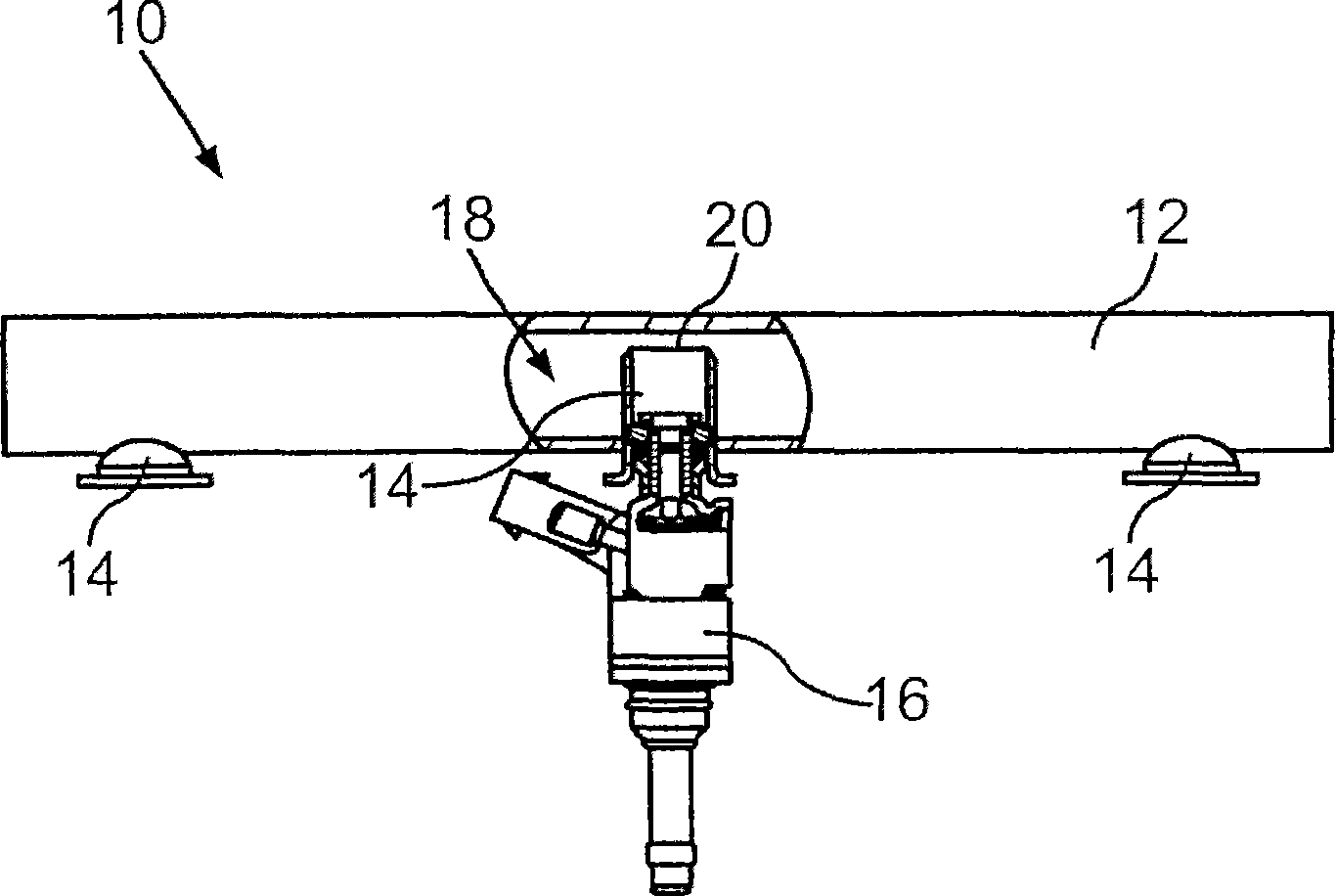
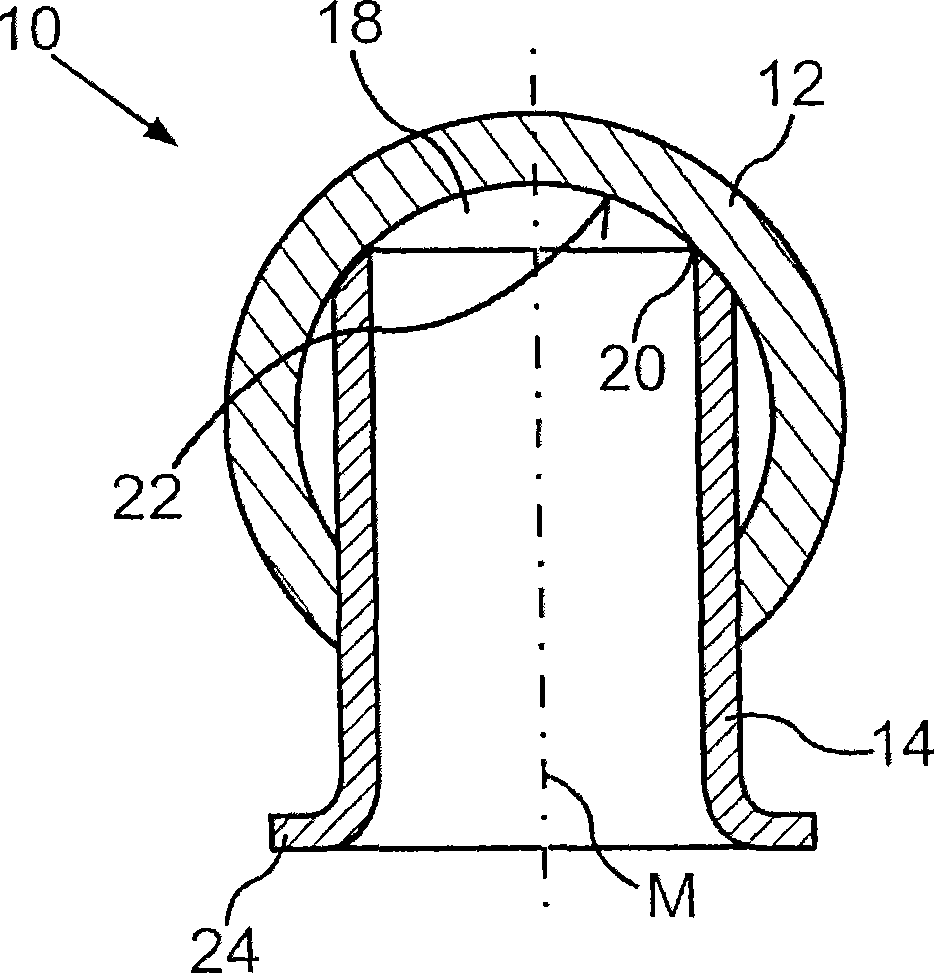
[0023] The fuel dispensing device 10 for a motor vehicle includes a fuel pipe 12 and a plurality of receiving pipes 14 , three of which are shown here by way of example. Each of the three receiving pipes 14 serves to receive an injector 16 via which fuel under high pressure is injected from the interior space 18 of the fuel pipe 12 into the combustion chamber (not shown) of the internal combustion engine .

[0024] Here, only a small part of each receiving tube 14 protrudes from the fuel tube 12 , whereas the main part of each receiving tube 14 is arranged in the interior space 18 of the fuel tube 12 . A particularly low installation space height of the fuel distribution device 10 can thus be achieved. The receiving pipe 14 is formed from a simple pipe section which is inserted into the fuel pipe 12 to such an extent that the end 20 of the receiving pipe 14 facing away from the injector 16 is in contact with the inner wall 22 of the fuel pipe 12 .

[0025] By tapering the re...


PUM


Abstract

#CMT# # / CMT# Fuel distribution device (10) comprises a fuel pipe (12) and pick-up tube (14), which are arranged with an injector (16). A receiving tube is also provided with interior space (18) of the fuel tube, where the intake pipe is introduced through front opening of the fuel tube. #CMT# : # / CMT# An independent claim is also included for a method for producing fuel distribution device. #CMT#USE : # / CMT# Fuel distribution device used for a motor vehicle. #CMT#ADVANTAGE : # / CMT# The fuel distribution device can be manufactured in a simple and cost-effective manner. #CMT#DESCRIPTION OF DRAWINGS : # / CMT# The drawing shows a partially sectional side view of a fuel distribution device with a fuel pipe. 10 : Fuel distribution device 12 : Fuel pipe 14 : Pick-up tube 16 : Injector 18 : Interior space.

Description

technical field [0001] The invention relates to a fuel distribution device for a motor vehicle having a fuel pipe and at least one receiving pipe arranged on the fuel pipe for an injector, wherein the receiving pipe protrudes partially into the interior of the fuel pipe. The at least one receiving tube has an end opening through which fuel can be introduced into the receiving tube. Furthermore, the invention relates to a method for producing such a fuel distribution device. Background technique [0002] US 6 935 314 B2 describes a fuel dispensing device for a motor vehicle, in which a plurality of receiving tubes are provided on the fuel line for each receiving an injector. The receiving pipe can be fixed outside the fuel pipe, or can extend into a section of the fuel pipe. Two chambers are provided in the fuel line for receiving gases formed during the operation of the fuel distribution device when the injector injects fuel into the engine cylinders. The gas in the chamb...

Claims


Application Information

Patent Timeline
Patent Type & Authority Patents(China)
IPC IPC(8): F02M55/02
CPCF02M55/02F02M69/465F02M55/025Y10T29/494
Inventor M·林德纳K·克里普纳
Owner AUDI AG
Why Eureka
Try Eureka