
Air cylinder and punching machine using same

A punching machine and air cylinder technology, applied in the field of the air cylinder of the punching machine, can solve the problems of increasing production cost, affecting the processing time, and the stability of the axial movement of the cylinder is difficult to meet the requirements, so as to improve production efficiency, prevent chattering, The effect of precise axial movement

Inactive Publication Date: 2014-12-31
SHENZHEN FUTAIHONG PRECISION IND CO LTD
View PDF7 Cites 0 Cited by
  • Summary
  • Abstract
  • Description
  • Claims
  • Application Information

AI Technical Summary

Problems solved by technology

[0002] With the rapid development of automation technology, the punching operation of various products can be completed by automatic punching machines. Most of the equipment uses cylinders as the driving force. However, the stability of the axial movement of the cylinders during the punching process is difficult to meet the requirements. In addition, it is necessary to set up a waste removal system, which affects the processing time and increases the production cost.

Method used


Image

  • Air cylinder and punching machine using same
  • Air cylinder and punching machine using same
  • Air cylinder and punching machine using same

Examples


Embodiment Construction

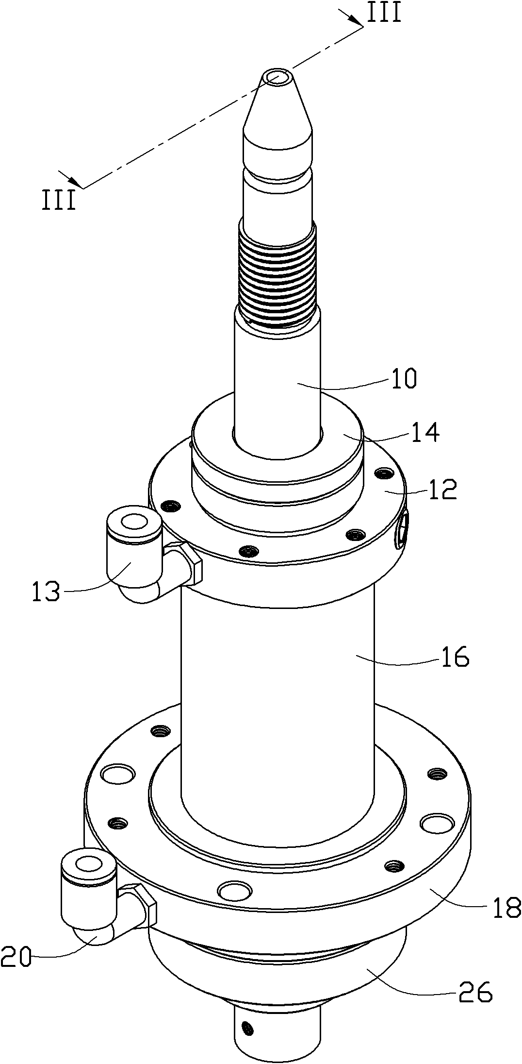
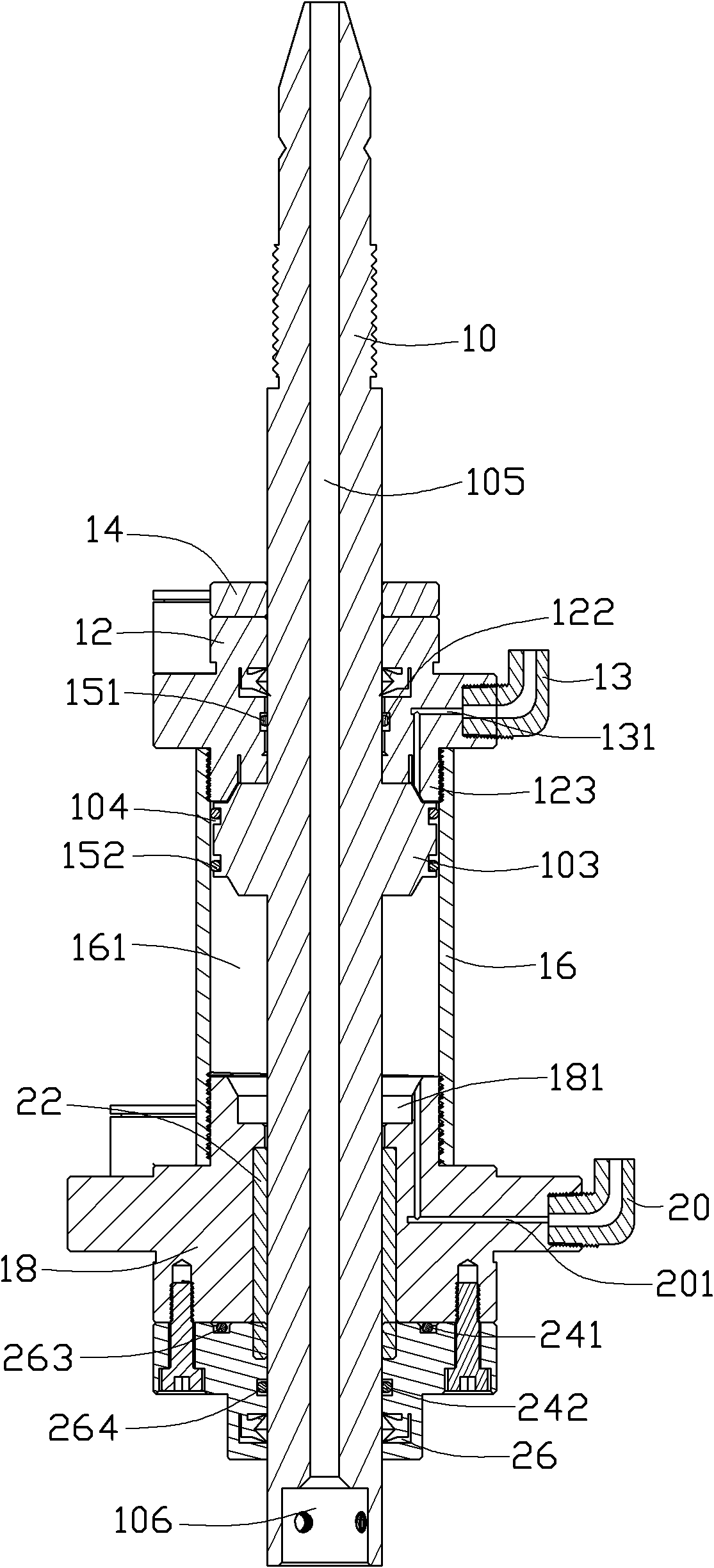
[0014] see figure 1 and figure 2 , the cylinder of the preferred embodiment of the present invention is used for the drive of the punching machine and removes waste materials, and it includes a piston rod 10, a rear end cover 12, a first joint 13, a buffer pad 14, a seal 15, a cylinder barrel 16, The front end cover 18 , the second joint 20 , the shaft sleeve 22 , the sealing member 24 and the fixing member 26 .

[0015] Please also refer to image 3 , the piston rod 10 is roughly a cylinder, which includes a front end 101 , a tail end 102 and a carrier 103 . The bearing body 103 is an annular disc located in the middle of the outer circle, which is larger than the diameter of the piston rod 10 . Two annular grooves 104 are recessed on the outer edge of the carrier 103 at intervals. A through hole 105 is defined along the axial direction of the piston rod 10 , passing through the front end 101 and the tail end 102 for removing waste materials. The front end 101 of the pi...


PUM


Abstract

The invention relates to an air cylinder, which comprises a piston rod, a rear end cover, a cylinder barrel, a front end cover, a fixed piece and a shaft sleeve, wherein the piston rod comprises a through hole; the through hole is used for discharging wastes; the shaft sleeve is arranged in the front end cover; the rear end cover is connected with the front end cover by the cylinder barrel; the rear end cover, the front end cover and the cylinder barrel are sleeved on the piston rod; and the fixed piece is sleeved on the piston rod and is fixedly connected with the front end cover. The invention also relates to a punching machine with the air cylinder.

Description

technical field [0001] The invention relates to a cylinder, in particular to a cylinder for a punching machine. Background technique [0002] With the rapid development of automation technology, the punching operation of various products can be completed by automatic punching machines. Most of the equipment uses cylinders as the driving force. However, the stability of the axial movement of the cylinders during the punching process is difficult to meet the requirements. In addition, it is necessary to set up a waste removal system, which affects the processing time and increases the production cost. Contents of the invention [0003] In view of this, it is necessary to provide a cylinder with high stability and capable of removing waste materials. [0004] It is also necessary to provide a punching machine with the cylinder. [0005] The cylinder includes a piston rod, a rear end cover, a cylinder barrel, a front end cover, a fixing piece and a shaft sleeve, the piston r...

Claims


Application Information

Patent Timeline
Patent Type & Authority Patents(China)
IPC IPC(8): F16J7/00F16J10/00
Inventor 阳柏林徐晓东
Owner SHENZHEN FUTAIHONG PRECISION IND CO LTD
Learn More