
Negative part structure of magnetron

A magnetron and cathode technology, applied in the field of magnetron, can solve the problems of shortening the service life of magnetron, damage of magnetron, low radiation rate, etc., to prolong the normal working life, avoid high voltage breakdown, eliminate sharp corner effect

Inactive Publication Date: 2011-11-09
LG ELECTRONICS (TIANJIN) APPLIANCES CO LTD
View PDF0 Cites 2 Cited by
  • Summary
  • Abstract
  • Description
  • Claims
  • Application Information

AI Technical Summary

Problems solved by technology

[0017] In the prior art cathode part structure of the magnetron, the shielding cap is a protruding circular platform structure arranged on the upper end of the upper seal, and the upper surface of the shielding cap is a circular plane. When the magnetron starts to work, the cathode part generates A large amount of heat, the thermal electrons generated by the filament are mainly emitted from the shielding cap at the upper end of the upper seal, that is, the thermal electrons are emitted through the upper surface formed by the circular plane of the shielding cap. The emissivity of the upper surface is small, which is easy to cause the shielding cap and The temperature of the cathode part of the entire magnetron is too high, thereby shortening the service life of the magnetron
In addition, since both the upper seal and the lower seal adopt a cylindrical structure, the intersection of the plane and the circumferential surface in the upper seal and the lower seal and the contact joint between the upper surface of the shielding cap and the upper seal form a relatively sharp These edges and corners are easy to lead to excessive voltage collection during the use of the magnetron, which will cause the magnetron to be damaged by high voltage breakdown

Method used


Image

  • Negative part structure of magnetron
  • Negative part structure of magnetron
  • Negative part structure of magnetron

Examples


Embodiment Construction

[0033] The present invention will be described in detail below in conjunction with the accompanying drawings and embodiments.

[0034] Figure 4 It is a schematic diagram of the structure of the cathode part of the magnetron of this invention.

[0035] Such as Figure 4As shown, the cathode cover of the magnetron is arranged at the lower part of the lower magnetic pole of the magnetron, and is sealed and connected with the anode shell of the magnetron to form a lower sealed chamber. The metal cathode cover and the anode shell are tightly connected by welding, and the cathode seal The middle position of the lower part of the cover is provided with an opening for the lead-out wire of the cathode to pass through. A ceramic component is arranged at the lower end of the magnetron corresponding to the lower sealing chamber of the lower magnetic pole, and the ceramic component is tightly combined with the cathode cover forming the lower sealing chamber; two cathode lead-out lines p...


PUM


Abstract

The invention relates to a negative part structure of a magnetron. A shielding cap with a smooth structure and an upper convex cambered surface is formed at the upper end of an upper sealing element; the surface area of the upper surface of the shielding cap is correspondingly increased, so that the radiance of the upper surface of the shielding cap is improved to make energy collected on a negative part of the magnetron timely and outwards diffused, cool the shielding cap and the whole negative part of the magnetron, enable the negative part of the magnetron to operate at normal temperature, avoid the damage to the magnetron caused by over-high temperature of the negative part, and prolong the normal service life of the magnetron. Arc bevel angles are positioned at junctions of all planes and circumference surfaces of the upper sealing element and a lower sealing element, the original closed angles on all parts of the negative part are eliminated, the magnetron is prevented from high-voltage breakdown caused by the closed angles, and a product fault caused by fire striking of the magnetron negative is avoided.

Description

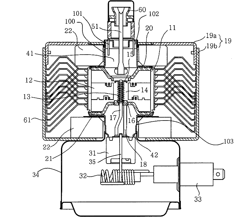
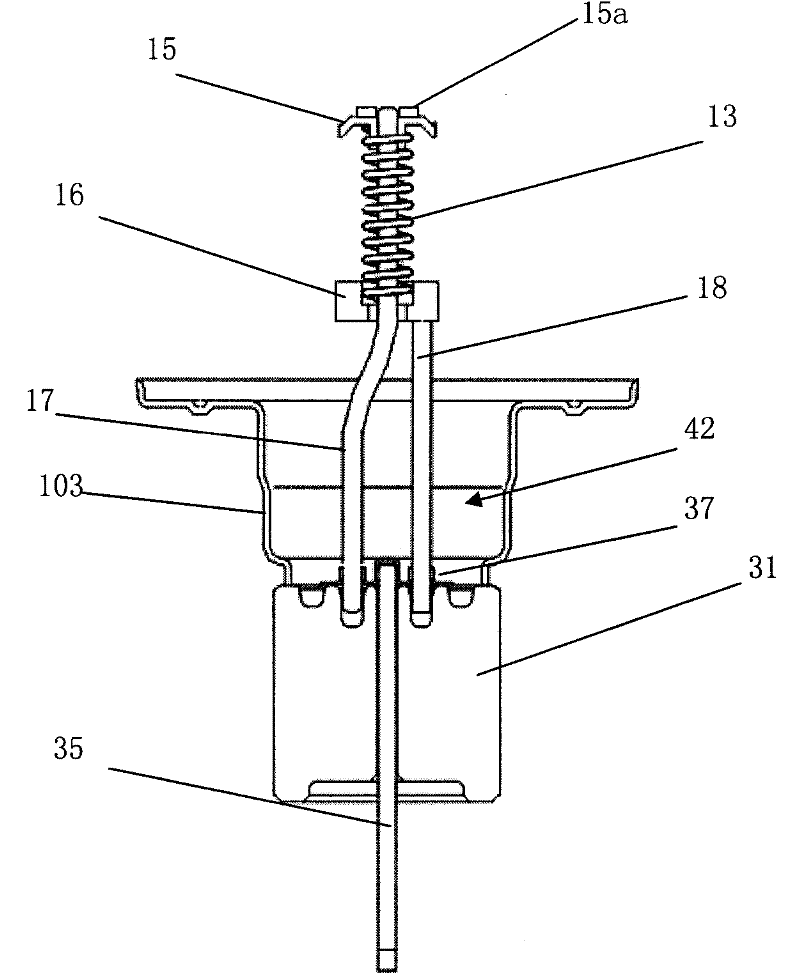
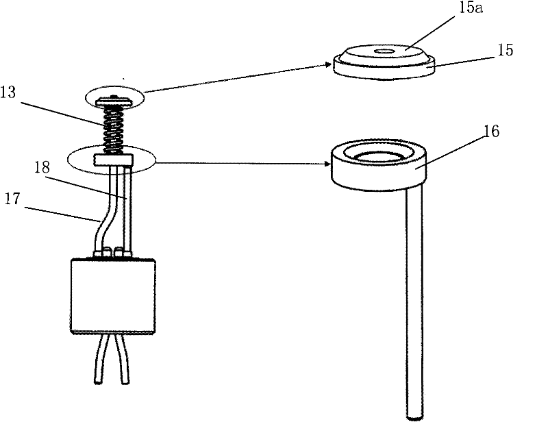
technical field [0001] The invention belongs to the technical field of magnetrons, and in particular relates to a shielding cap with an arc-shaped upper surface, and chamfers are provided to remove the edges and corners on the upper and lower sealing parts respectively, so as to improve the thermal electron radiation rate and avoid high voltage shock The structure of the cathode part of the magnetron. Background technique [0002] figure 1 It is a longitudinal sectional view of a magnetron structure in the prior art; figure 2 is a cross-sectional view of the structure of the cathode part of the magnetron in the prior art; image 3 It is a schematic diagram of the structure of the cathode part of the magnetron in the prior art. [0003] Such as Figure 1 to Figure 3 As shown, the magnetron mainly includes: an anode part; a cathode part; a magnetic pole part; a microwave emitting part. [0004] The anode part consists of a barrel-shaped anode shell 11, on the inner wall ...

Claims


Application Information

Patent Timeline
Patent Type & Authority Applications(China)
IPC IPC(8): H01J23/04
Inventor 王媛李忆
Owner LG ELECTRONICS (TIANJIN) APPLIANCES CO LTD
Learn More