Automatic debugging system for radio frequency module

A radio frequency module and automatic debugging technology, which is applied in the direction of control/regulation system, transmission system, general control system, etc., can solve the problems of batchability impact, product quality and reportability, and achieve the goal of improving production efficiency Effect

Inactive Publication Date: 2011-11-09
JIALV COMM EQUIP SHANGHAI
View PDF3 Cites 0 Cited by
  • Summary
  • Abstract
  • Description
  • Claims
  • Application Information

AI Technical Summary

Problems solved by technology

[0004] 1: The frequent use of soldering iron will bring potential problems to the quality and noticeability of the product;
[0005] 2: Due to differences in devices or environmental reasons, due to product consistency, the ability to batch is greatly affected

Method used


Image

  • Automatic debugging system for radio frequency module
  • Automatic debugging system for radio frequency module

Examples


Embodiment

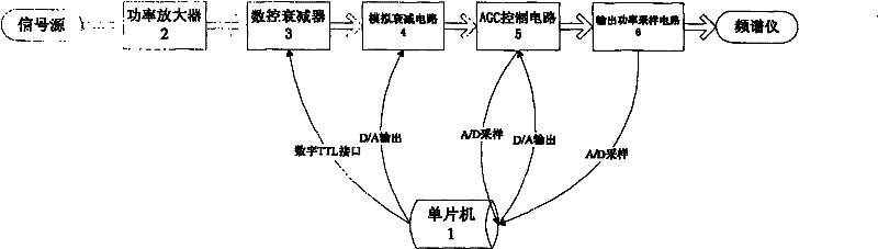
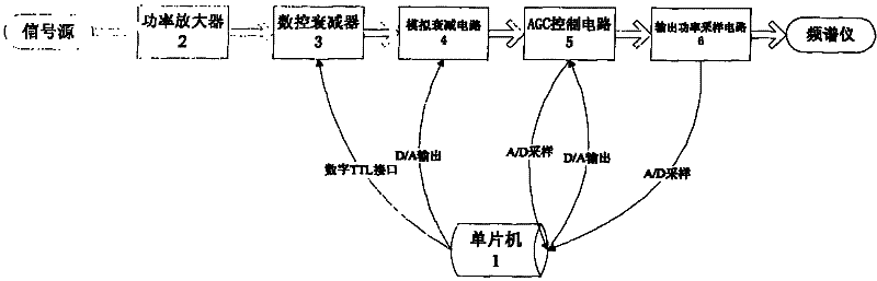
[0017] like figure 1 As shown, an automatic debugging system of a radio frequency module includes a radio frequency shielding module, a monitoring circuit, and an RS485 bus. The radio frequency module is connected to the monitoring circuit through the RS485 bus. The radio frequency module includes a power amplifier 2 and a digitally controlled attenuator 3 , analog attenuation circuit 4, AGC control circuit 5, output power sampling circuit 6, described monitoring circuit comprises single-chip microcomputer 1, RS485 converter, analog-to-digital converter, digital-to-analog converter, described power amplifier 2, numerical control attenuator 3, analog attenuation circuit 4, AGC control circuit 5, output power sampling circuit 6 are connected successively, described single-chip microcomputer 1 is connected with AGC control circuit 5, output power sampling circuit 6 respectively by analog-to-digital converter, described single-chip microcomputer 1 is respectively It is connected w...


PUM


Abstract

The invention relates to an automatic debugging system for a radio frequency module. The automatic debugging system comprises the radio frequency module, a monitoring circuit and an RS485 bus, wherein the radio frequency module is connected with the monitoring circuit by the RS485 bus, and comprises a power amplifier, a numerically controlled attenuator, an analogue attenuation circuit, an automatic gain control (AGC) circuit and an output power sampling circuit; the monitoring circuit comprises a singlechip, an RS485 converter, an analogue-to-digital converter and a digital-to-analogue converter; the power amplifier, the numerically controlled attenuator, the analogue attenuation circuit, the AGC circuit and the output power sampling circuit are connected in turn; and the singlechip is connected with the AGC circuit and the output power sampling circuit by the analogue-to-digital converter respectively, and is connected with the analogue attenuation circuit and the AGC circuit by the digital-to-analogue converter respectively. Compared with the prior art, the automatic debugging system has the advantages of calibration automation, high production efficiency and the like.

Description

technical field [0001] The invention relates to a radio frequency module debugging system, in particular to an automatic debugging system of a radio frequency module. Background technique [0002] At present, the radio frequency modules in the communication are manually debugged or tested by the relevant technical personnel in the production of the corresponding radio frequency and monitoring specifications. [0003] According to different customer requirements, artificially add or remove devices or modify device values. Its disadvantages: [0004] 1: The frequent use of soldering iron will bring potential problems to the quality and noticeability of the product; [0005] 2: Due to differences in devices or environmental reasons, due to product consistency, the ability to batch is greatly affected. Contents of the invention [0006] The object of the present invention is to provide an automatic debugging system for radio frequency modules with automatic calibration and ...

Claims


Application Information

Patent Timeline
Patent Type & Authority Applications(China)
IPC IPC(8): H04B1/38G05B19/042H04B17/00
Inventor 许汉铭
Owner JIALV COMM EQUIP SHANGHAI
Why Eureka
Try Eureka