
Guide sleeve of forging press

A technology of guide sleeve and forging press, applied in the field of guide sleeve, can solve the problems of large wear of guide sleeve, decreased guiding effect, unstable structure, etc., and achieves the effects of stable operation of equipment, reduction of force and friction, and improvement of utilization rate.

Inactive Publication Date: 2011-11-16
无锡市乾丰锻造有限公司
View PDF4 Cites 10 Cited by
  • Summary
  • Abstract
  • Description
  • Claims
  • Application Information

AI Technical Summary

Problems solved by technology

[0002] The large-scale forging press uses the plunger to forge the object, and the plunger is fixed by the mounting bracket and the column of the forging press. In order to ensure that the plunger maintains balance during the forging process and does not produce eccentricity, the installation must ensure that the plunger mounting bracket and the column can To adapt to the effect of relative stress, generally under the premise of ensuring the fast connection between the mounting bracket and the column, guide sleeves are provided at the connection part to avoid excessive force on the joint and the column and breakage. Now the general guide sleeve is a circular guide set around the column This structure can avoid excessive force on the contact area, but due to the large force, the wear of the guide sleeve is relatively large. The existing guide sleeve will greatly reduce the guiding effect after being worn for a certain period of time. It is time-consuming and labor-intensive to replace the entire guide sleeve, and the pressure plate used with the guide sleeve can be connected and fixed with the mounting bracket by fastening bolts. The existing pressure plate is a whole ring-shaped pressure plate, and the ring part is pressed Pressing on the guide sleeve, because the pressure plate needs to bear a relatively large pressure, and the force is due to the reciprocating movement of the plunger, the pressure-bearing part will also change. This overall structure is prone to unstable structure when the force is large. cause break

Method used


Image

  • Guide sleeve of forging press
  • Guide sleeve of forging press
  • Guide sleeve of forging press

Examples


Embodiment Construction

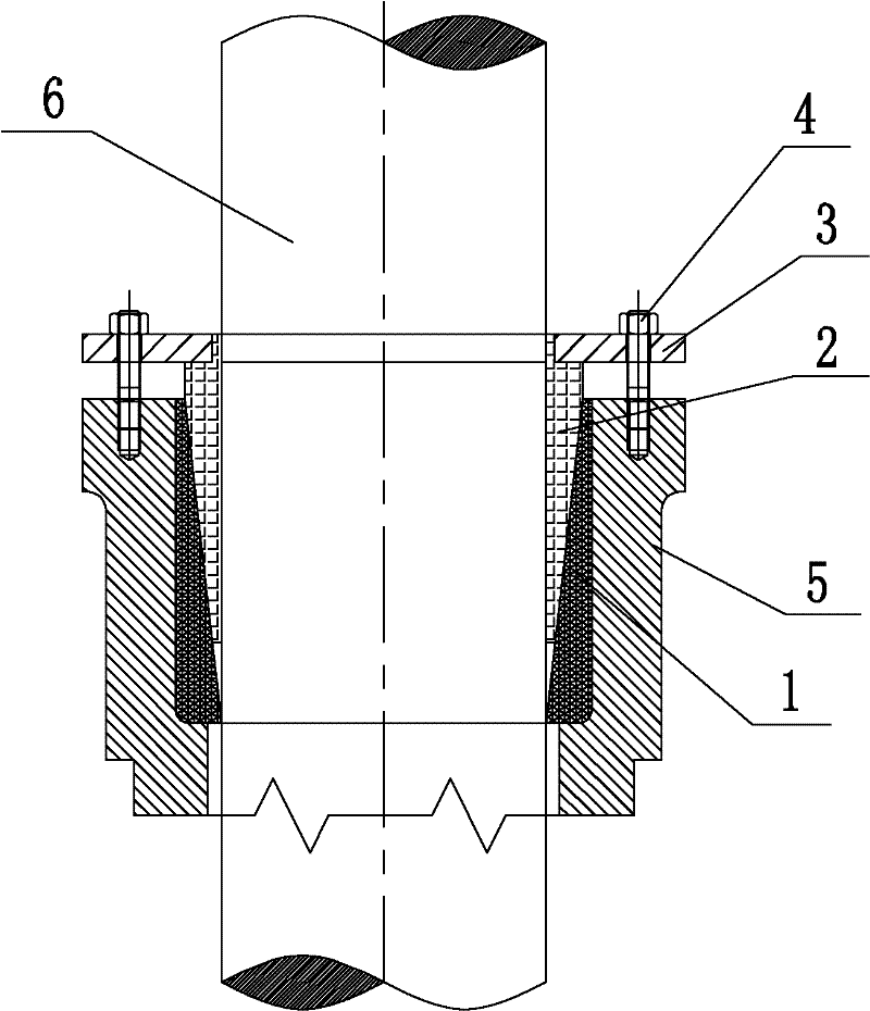
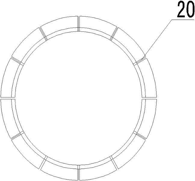
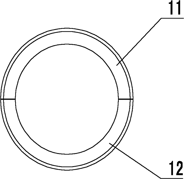
[0022] see figure 1 , the adjustable guide sleeve of the present invention includes a fixed guide sleeve 1, a movable guide sleeve 2, a pressure plate 3 and a compression bolt 4, wherein the fixed guide sleeve 1 is fixed between the mounting bracket 5 and the column 6 to ensure that the outer surface and The mounting bracket 5 is closely matched, and the movable guide sleeve 2 is pressed between the fixed guide sleeve 1 and the column 6 with the pressure plate 3, so that the column 6 will not shake, and the pressure plate 3 and the mounting bracket 5 are fastened with the compression bolt 4, and the pressure plate The material is during production, because the column 6 will be subjected to a large stress brought by the plunger, and the inner surface of the movable guide sleeve 2 will be worn to a certain extent. 2. Press into the movable gap between the fixed guide sleeve 1 and the column 6. According to production experience, the press-in value of the adjustable guide sleeve ...


PUM


Abstract

The invention provides a guide sleeve of a forging press. The guide sleeve is an annular guide sleeve composed of a fixed guide sleeve and a movable guide sleeve. The fixed guide sleeve and the movable guide sleeve are in wedge-shaped fit. The movable guide sleeve is arranged at inner side of the fixed guide sleeve and can move along an inclined surface. The inside surface of the movable guide sleeve is contacted with a forging press upright post. The outside surface of the fixed guide sleeve is contacted with a forging press machine frame. According to the guide sleeve of the forging press disclosed by the invention, the fixed guide sleeve and the movable guide sleeve, which are matched with each other, are used; the original structure can be still kept continuously after being worn; and the guide sleeve can be prevented from being replaced frequently.

Description

technical field [0001] The invention relates to a guide sleeve, in particular to a column guide sleeve of a forging press. Background technique [0002] The large-scale forging press uses the plunger to forge the object, and the plunger is fixed by the mounting bracket and the column of the forging press. In order to ensure that the plunger maintains balance during the forging process and does not produce eccentricity, the installation must ensure that the plunger mounting bracket and the column can To adapt to the effect of relative stress, generally under the premise of ensuring the fast connection between the mounting bracket and the column, guide sleeves are provided at the connection part to avoid excessive force on the joint and the column and breakage. Now the general guide sleeve is a circular guide set around the column This structure can avoid excessive force on the contact area, but due to the large force, the wear of the guide sleeve is relatively large. The exis...

Claims


Application Information

Patent Timeline
IPC IPC(8): B21J13/00
Inventor 周东平
Owner 无锡市乾丰锻造有限公司
Learn More