Eureka AIR delivers breakthrough ideas for toughest innovation challenges, trusted by R&D personnel around the world.

Novel friction type clutch brake mechanism of steel plate shearer

A clutch brake, shearing machine technology, applied in the combination of couplings and brakes, shearing devices, mechanical equipment, etc., can solve the problems of production shutdown and maintenance, consumption of manpower, material resources, financial resources, and prone to broken teeth

Inactive Publication Date: 2011-11-16
李向普
View PDF5 Cites 2 Cited by
  • Summary
  • Abstract
  • Description
  • Claims
  • Application Information

AI Technical Summary

Problems solved by technology

When the shearing machine is shearing, only two points on the large gear are stressed, and the brake stops at the top dead center when it stops. In this way, under the impact of inertia, it is easy to break the teeth, resulting in shutdown for maintenance and consumption. Human, material and financial resources affect production efficiency

Method used


Image

  • Novel friction type clutch brake mechanism of steel plate shearer
  • Novel friction type clutch brake mechanism of steel plate shearer
  • Novel friction type clutch brake mechanism of steel plate shearer

Examples


Embodiment Construction

[0016] This embodiment is a clutch brake mechanism containing two friction plates. The purpose of disclosing the present invention is to protect all improvements within the scope of the present invention, and the present invention is not limited to the following embodiments.

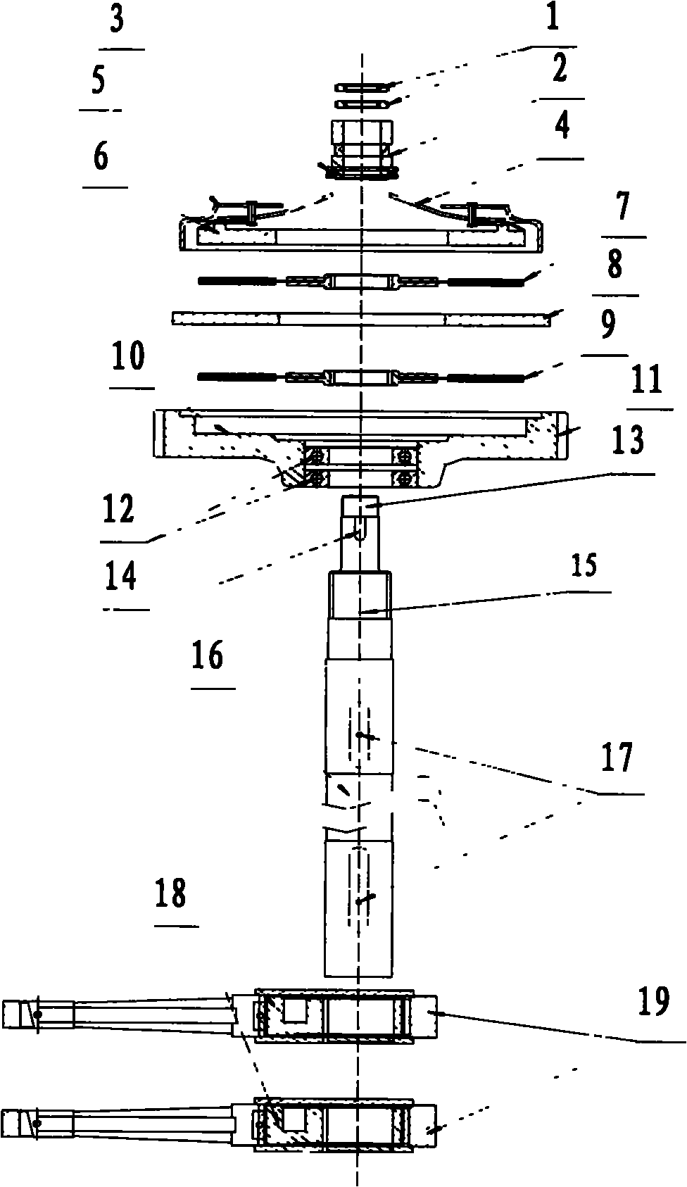
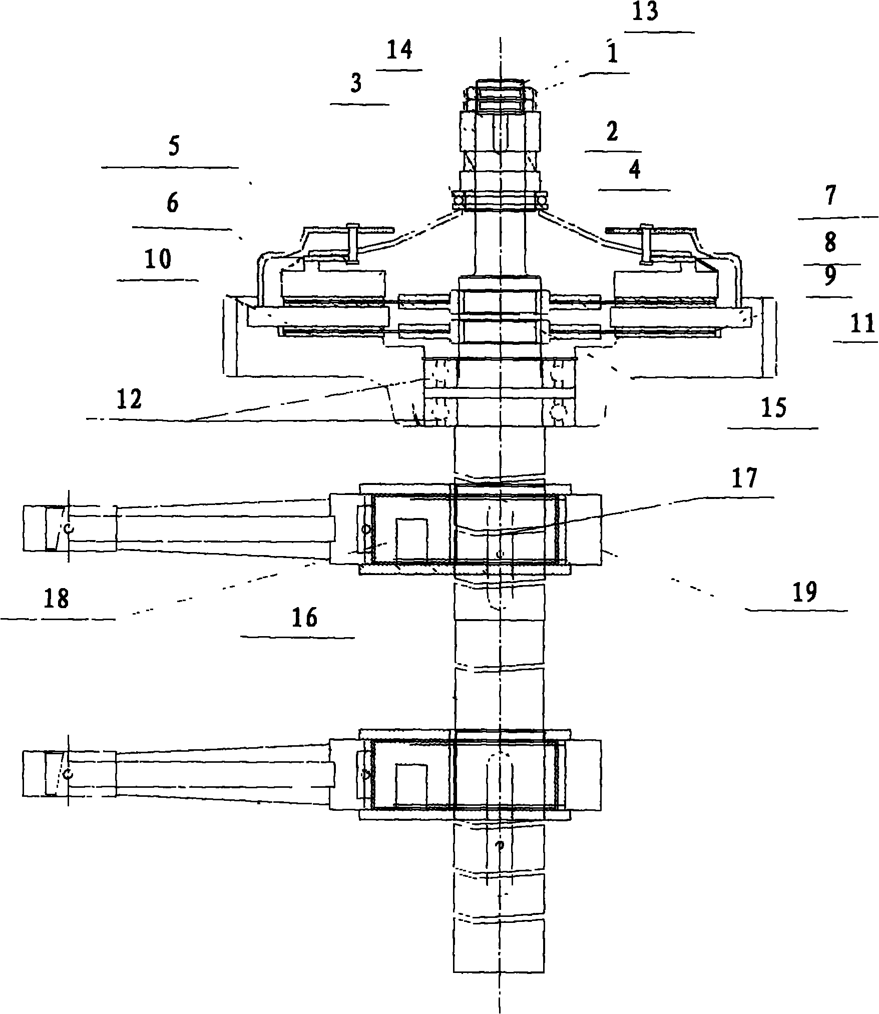
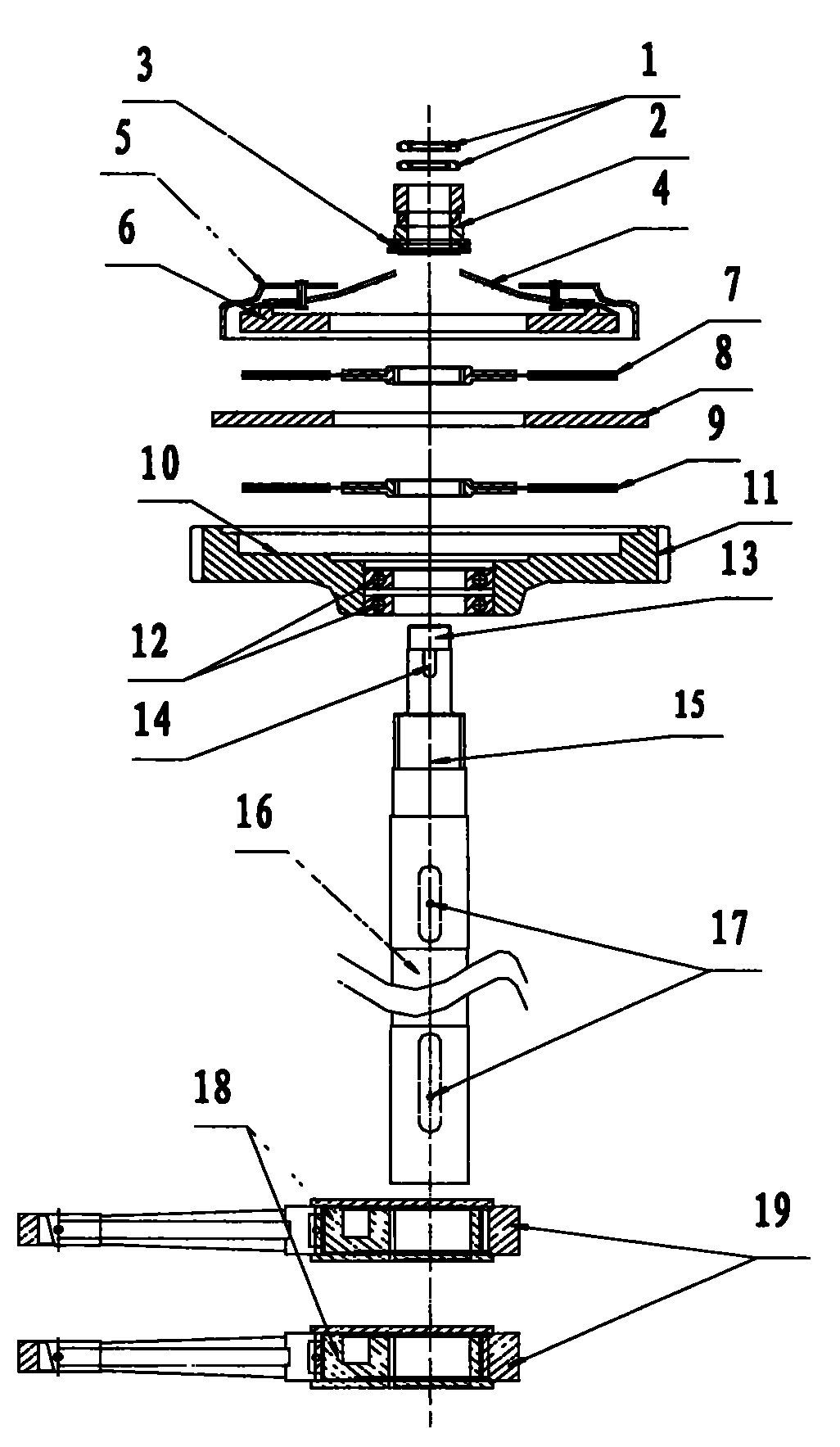
[0017] figure 1 , figure 2 The structure of the shearing machine friction brake of this embodiment is shown respectively from assembly and actual structure.

[0018] The friction brake mechanism of the shearing machine of this embodiment comprises the main shaft 16 of the shearing machine, the eccentric wheel 18, and the rod 19. The axial direction of the main shaft 16 is provided with two keyways 17, and the two eccentric wheels 18 are respectively sleeved on the On the keyway 17, and fixed by the key. A bearing 12 is sleeved on one side of the main shaft; the outer edge surface of the bearing 12 is in interference fit with the large gear 11, the outer surface of the large gear 11 is the gear frictio...


PUM


Abstract

The invention discloses a novel friction type clutch brake mechanism of a steel plate shearer. A ratchet wheel key slot and an eccentric bushing key slot are respectively arranged on the spindle of the steel plate shearer, and two eccentric wheels are respectively sheathed on the spindle provided with the key slot; one side of a pressure plate assembly is tightly contacted with an external friction disk, the other side of the pressure plate assembly is annularly tightly contacted with a friction disk arranged inside a pressure plate spring, and the pressure plate spring and the friction disk are connected with the interior of the pressure plate assembly; and a separation ratchet wheel is sheathed on the outer thread of the spindle outside a spline shaft. In the friction brake clutch mechanism of the steel plate shearer disclosed by the invention, the hub type brake system of the traditional steel plate shearer is changed into a friction brake, and a pressure plate shell is combined with an inner friction disk and an outer friction disk to cause a clutch to stably buffer friction, damage of overload to a gear during shearing by adopting the brake mechanism of the traditional steel plate shearer can be effectively overcome, and the service life of the clutch is greatly prolonged.

Description

【Technical field】 [0001] The invention relates to a clutch brake mechanism of a shearing machine, in particular to a friction clutch brake mechanism of a shearing machine. 【Background technique】 [0002] The shearing machine is often used to cut the straight edge of the sheet, and obtain the sheet whose size meets the design requirements by cutting. The shearing process should be able to ensure the straightness and parallelism of the sheared surface of the sheet to be cut, and minimize the distortion of the sheet. [0003] The mechanical shearing machine is a kind of shearing machine widely used at present, with simple structure, low cost and high work efficiency. The two ends of the main shaft are respectively equipped with a clutch mechanism and a brake mechanism: the main shaft clutch system is connected by a rotary key, and the clutch mechanism is mainly composed of a rotary key (or square key), a clutch disc, an inlaid steel, and a switch blade; the brake mechanism is ...

Claims


Application Information

Patent Timeline
IPC IPC(8): B23D15/12F16D67/02
Inventor 李向普
Owner 李向普
Why Eureka
Eureka Blog
Learn More