Handheld electric angle grinder

A technology for electric angle grinding machines, applied in grinding machines, portable grinding machines, grinding/polishing equipment, etc., which can solve problems affecting the operation reliability of the brushed motor 3' and the wear and tear of the commutator 31', so as to improve the operation More reliable performance and reliable operation

Inactive Publication Date: 2011-11-16
福建惠安县坚固电机有限公司
View PDF9 Cites 4 Cited by
  • Summary
  • Abstract
  • Description
  • Claims
  • Application Information

AI Technical Summary

Problems solved by technology

[0004] Among them, the brushed motor 3' adopts a commonly used brushed motor on the market, including a commutator 31', a carbon brush 32' and a brush holder 33', and the carbon brush 32' is fixed on the stator shell 1' through the brush holder 33'. The commutator 31' and the carbon brush 32' cooperate with each other, and there is a problem of serious wear of the commutator 31', which affects the operation reliability of the brushed motor 3' to a large extent

Method used


Image

  • Handheld electric angle grinder
  • Handheld electric angle grinder
  • Handheld electric angle grinder

Examples


Embodiment 1

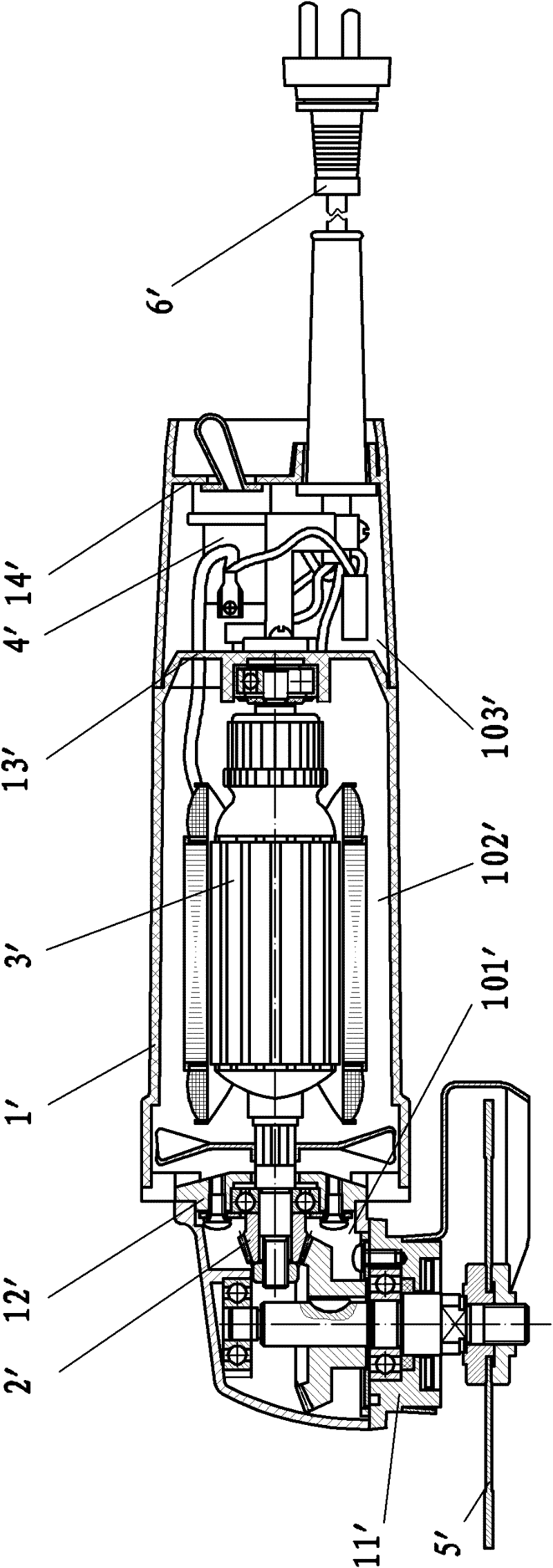
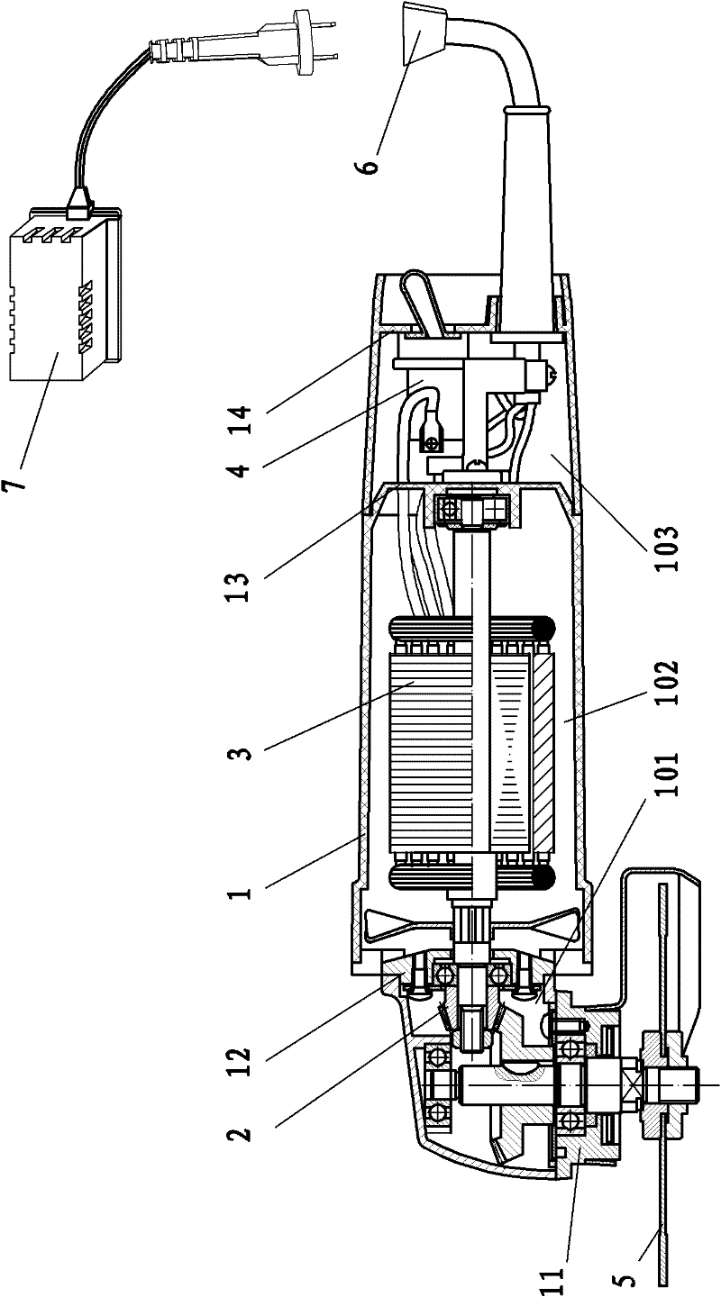
[0045] Such as Figure 3-4 As shown, the handheld electric angle grinder of the present invention includes a stator case 1 , a transmission assembly 2 , a three-phase asynchronous motor 3 , a control circuit 4 , a grinding wheel 5 , a power interface 6 and an electronic control unit 7 .

[0046] The stator case 1 is divided into a transmission chamber 101, a motor chamber 102 and a circuit chamber 103 through the front cover 11, the middle cover 12, the bearing chamber 13 and the rear cover 14 in sequence from front to back; the transmission assembly 2 is arranged in the transmission chamber 101, The three-phase asynchronous motor 3 is arranged in the motor chamber 102 , the control circuit 4 of the three-phase asynchronous motor 3 is arranged in the circuit chamber 103 , and the power interface 6 is arranged on the rear cover 14 . The transmission assembly 2 mainly includes a pinion 22 , an output shaft 23 and a bull gear 25 . The rotating shaft 31 of the three-phase asynchr...

Embodiment 2

[0056] The main difference between this embodiment and Embodiment 1 lies in the location of the electronic control unit. In this embodiment, the electronic control unit is located in the stator housing, and the electronic control unit is electrically connected to the control circuit of the high-frequency motor through a corresponding port.


PUM


Abstract

The invention discloses a handheld electric angle grinder which comprises a stator shell and an electric control unit, wherein the stator shell is correspondingly divided into a transmission cavity, a motor cavity and a circuit cavity by a front cover, a middle cover, a bearing chamber and a rear cover in turn from front to back; a transmission component is arranged in the transmission cavity; a motor is arranged in the motor cavity; a control circuit of the motor is arranged in the circuit cavity; a power interface is arranged on the rear cover; the control circuit is electrically connected to a corresponding port of the power interface; a rotating shaft of the motor is connected to an output shaft of the transmission component; after the output shaft of the transmission component extends out of the front cover, a grinding wheel is arranged on end part of the output shaft; the motor is a three-phase asynchronous motor; the electric control unit is positioned outside the stator shell; and the electric control unit is electrically connected to the control circuit of the high-frequency three-phase asynchronous motor through the corresponding port of the power interface. The invention also discloses a handheld electric angle grinder, the electric control unit of which is arranged in the stator shell. The handheld electric angle grinder provided by the invention has no commutator and is more reliable in running.

Description

technical field [0001] The invention relates to a hand-held electric grinding tool, in particular to a hand-held electric angle grinder. Background technique [0002] At present, electric angle grinders are commonly used as hand-held tools for workers, mainly using high-speed rotating sheet-type grinding wheels to grind, cut, derust, and polish metals and stones. Existing angle grinders such as Figure 1-2 As shown, it includes a stator shell 1', a transmission assembly 2', a brushed motor 3', an electronic control unit 4', a grinding wheel piece 5' and a power interface 6'. The stator case 1' is divided into a transmission cavity 101', a motor cavity 102' and a circuit cavity 103' through the front cover 11', the middle cover 12', the bearing chamber 13' and the rear cover 14' in sequence from front to back; The transmission assembly 2' is arranged in the chamber 101', the brush motor 3' is arranged in the motor chamber 102', and the electric control unit 4' is arranged in...

Claims


Application Information

Patent Timeline
Patent Type & Authority Applications(China)
IPC IPC(8): B24B23/02
Inventor 曾细杰
Owner 福建惠安县坚固电机有限公司
Why Eureka
Try Eureka