High-efficient transmission energy-saving brick making machine

A brick machine, high-efficiency technology, applied in the field of high-efficiency transmission and energy-saving brick machines, can solve the problems of large radial displacement and certain angular displacement, can not guarantee the installation accuracy, increase the load of the reducer, etc., to reduce the amount of bearings, improve mechanical transmission Efficiency, effect of eliminating additional load

Inactive Publication Date: 2014-07-02
SICHUAN SANQIAO SPEED REDUCER
View PDF4 Cites 0 Cited by
  • Summary
  • Abstract
  • Description
  • Claims
  • Application Information

AI Technical Summary

Problems solved by technology

[0002] The output shaft of the reducer in the existing brick machine and the reamer of the brick machine are usually indirectly connected by a clamp coupling or a slider coupling. The clamp coupling has extremely high requirements for installation and requires strict and precise alignment of the connected two shafts. , otherwise it will cause a huge additional load, resulting in energy consumption
However, due to the poor working conditions of the working machine, irregular equipment installation or poor rigidity of the equipment base material, in actual operation, the installation accuracy can hardly be guaranteed, resulting in large radial displacement and certain angular displacement. It is very easy to damage the coupling or increase the load of the reducer
Due to the limitation of its structure, the slider coupling cannot be separated radially, but can only be separated along the axial direction, which is not easy to disassemble.
The connection method of the coupling needs to make a coupling support frame, which not only takes up a lot of space, but also consumes a lot of steel, which increases the manufacturing cost
Moreover, this connection method has a long transmission path and low transmission efficiency

Method used


Image

  • High-efficient transmission energy-saving brick making machine

Examples


Embodiment Construction

[0017] The present invention will be described in detail below in conjunction with the drawings.

[0018] In order to make the objectives, technical solutions and advantages of the present invention clearer, the following further describes the present invention in detail with reference to the accompanying drawings and embodiments. It should be understood that the specific embodiments described herein are only used to explain the present invention, but not to limit the present invention.

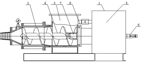
[0019] Such as figure 1 As shown, a high-efficiency transmission energy-saving brick machine includes a speed reducer 1 and a brick machine 2. The brick machine 2 includes a brick machine body 3 and a screw cutter 4, and the speed reducer 1 includes a box body 5, an input shaft 6 and The output shaft 7, the shaft end of the output shaft 7 is provided with an output shaft head matching the structure of the connecting end of the spiral cutter 4, and the output shaft head is in the shape of a polygo...


PUM


Abstract

The invention discloses a high-efficient transmission energy-saving brick making machine, which comprises a speed reducer and a brick making machine, wherein the brick making machine comprises a brick making machine body and a spiral reamer; the speed reducer is connected with the brick making machine body; and the output end of the speed reducer is connected with the spiral reamer of the brick making machine. In the machine, the output shaft of the speed reducer is directly connected with the spiral reamer of the brick making machine, so that the machine effectively improves transmission efficiency, is more reliably operated, saves energy and reduces consumption; and the machine has a simple structure and low manufacturing cost and is convenient to mount and dismount.

Description

Technical field [0001] The invention relates to brick making equipment, in particular to a high-efficiency transmission energy-saving brick machine. Background technique [0002] The output shaft of the reducer in the existing brick machine and the brick machine reamer are usually indirectly connected by a clamp shell coupling or a slider coupling. The clamp shell coupling has extremely high installation requirements and requires strict and precise centering of the two shafts. , Otherwise it will cause a great additional load and energy consumption. However, due to the poor working conditions of the working machine, the improper installation of the equipment or the poor rigidity of the equipment base material, in actual operation, the installation accuracy can hardly be guaranteed, resulting in a large radial displacement and a certain angular displacement. It is very easy to damage the coupling or increase the load of the reducer. However, the slider coupling is restricted by ...

Claims


Application Information

Patent Timeline
Patent Type & Authority Patents(China)
IPC IPC(8): B28B3/20
Inventor 陶文
Owner SICHUAN SANQIAO SPEED REDUCER
Why Eureka
Try Eureka