Heater improvement apparatus in ingot furnace producing quasi-single crystal silicon with casting method
A heater and casting method technology, which is applied to the heater heating device in the ingot furnace, and the field of the heater improvement device in the furnace similar to the single crystal silicon ingot produced by the casting method, can solve the problems of high cost, melting of the single crystal seed crystal, etc. The effect of reducing production costs and reducing the height of seed crystals
- Summary
- Abstract
- Description
- Claims
- Application Information
AI Technical Summary
Problems solved by technology
Method used
Image

Examples
Embodiment 1
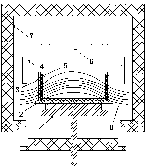
[0021] Such as figure 1 , 2 As shown, the heat conduction block 1 is placed at the bottom of the graphite bottom guard plate 2, and the ceramic crucible 5 is placed on the graphite bottom guard plate 2; the side of the ceramic crucible 5 is provided with a graphite guard plate 3; The heater 4 is provided with a top heater 6 above the ceramic crucible 5; a thermal insulation cage 7 is provided around the side heater 4 and the top heater 6; the simulated isothermal curve 8 formed is as shown in the figure.
[0022] figure 1 The position of the side heater 4 is: the distance from the upper edge of the side heater 4 to the top heater 6 is 15-30 cm.
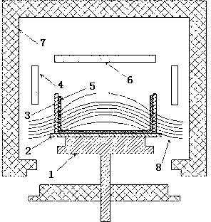
[0023] figure 2 and figure 1 The difference is in the side heater 4 boost.
[0024] The side heater 4 moves upwards by 5-10mm on the existing position. Such as 10 mm.
[0025] The single-sided monolithic resistance of side heater 4 is adjusted from 0.03Ω to 0.04~0.05Ω. Such as 0.04Ω.
Embodiment 2
[0027] Such as figure 1 , 2 As shown, the heat conduction block 1 is placed at the bottom of the graphite bottom guard plate 2, and the ceramic crucible 5 is placed on the graphite bottom guard plate 2; the side of the ceramic crucible 5 is provided with a graphite guard plate 3; The heater 4 is provided with a top heater 6 above the ceramic crucible 5; a thermal insulation cage 7 is provided around the side heater 4 and the top heater 6; the simulated isothermal curve 8 formed is as shown in the figure.
[0028] figure 1 The position of the side heater 4 is: the distance from the upper edge of the side heater 4 to the top heater 6 is 15-30 cm.
[0029] figure 2 and figure 1 The difference is in the side heater 4 boost.
[0030] The side heater 4 moves up 140~150mm on the existing position. Such as 150mm.
[0031] The single-sided monolithic resistance of side heater 4 is adjusted from 0.03Ω to 0.07~0.08Ω. Such as 0.08Ω.
Embodiment 3
[0033] Such as figure 1 , 2 As shown, the heat conduction block 1 is placed at the bottom of the graphite bottom guard plate 2, and the ceramic crucible 5 is placed on the graphite bottom guard plate 2; the side of the ceramic crucible 5 is provided with a graphite guard plate 3; The heater 4 is provided with a top heater 6 above the ceramic crucible 5; a thermal insulation cage 7 is provided around the side heater 4 and the top heater 6; the simulated isothermal curve 8 formed is as shown in the figure.
[0034] figure 1 The position of the side heater 4 is: the distance from the upper edge of the side heater 4 to the top heater 6 is 15-30 cm.
[0035] figure 2 and figure 1 The difference is in the side heater 4 boost.
[0036] Side heater 4 moves up 80mm on existing position.
[0037] The single-sided monolithic resistance of the side heater 4 is adjusted from 0.03Ω to 0.05Ω.
PUM
| Property | Measurement | Unit |
|---|---|---|
| electrical resistance | aaaaa | aaaaa |
| electrical resistance | aaaaa | aaaaa |
Abstract
Description
Claims
Application Information
 - R&D
- Intellectual Property
- Life Sciences
- Materials
- Tech Scout
- Unparalleled Data Quality
- Higher Quality Content
- 60% Fewer Hallucinations
Browse by: Latest US Patents, China's latest patents, Technical Efficacy Thesaurus, Application Domain, Technology Topic, Popular Technical Reports.
© 2025 PatSnap. All rights reserved.Legal|Privacy policy|Modern Slavery Act Transparency Statement|Sitemap|About US| Contact US: help@patsnap.com