Method for producing similar mono-crystalline silicon by using casting process

A casting method and single crystal silicon technology, applied in the field of crystal growth, can solve the problems of inability to produce similar single crystals in ingot furnace, chemical materials and the growth isotherm curve is not flat enough, so as to improve the low photoelectric conversion efficiency and improve the photoelectric conversion efficiency. , the effect of reducing defects

Inactive Publication Date: 2012-01-18
ANYANG PHOENIX PHOTOVOLTAIC TECH +1
View PDF0 Cites 10 Cited by
  • Summary
  • Abstract
  • Description
  • Claims
  • Application Information

AI Technical Summary

Problems solved by technology

The simulated isotherm curve 8 formed before the improvement is as figure 1 shown by figure 1 It can be seen that the chemical material and growth isotherm curves are not flat enough
It shows that if the temperature gradient of the thermal field is not improved, it will not be possible to produce similar single crystals (quasi-single crystals) with ingot furnaces with GT or four-sided and top heaters
This is why, so far, no manufacturers of ingot furnaces using GT or four-sided and top heaters have announced that they can produce quasi-single crystals

Method used


Image

  • Method for producing similar mono-crystalline silicon by using casting process
  • Method for producing similar mono-crystalline silicon by using casting process
  • Method for producing similar mono-crystalline silicon by using casting process

Examples


Embodiment 1

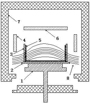
[0083] Such as figure 2As shown, the heat conduction block 1 is placed under the crucible bottom guard plate 2 (the bottom guard plate is generally made of graphite material), and the crucible bottom guard plate 2 is placed on the crucible 5 (generally a ceramic crucible); the four sides of the crucible 5 are set There are crucible side guards 3 (the side guards are generally made of graphite); a side heater 4 is arranged above the crucible 5 (the height of the crucible 5 is generally 400mm to 600mm, and can be increased if necessary). Top heater 6 is arranged on the top; Heat insulation cage 7 is arranged around side heater 4 and top heater 6, wherein the heat insulation cage 7 below is fixed, and the heat insulation cage 7 of surroundings is integrated above and can be promoted.

[0084] The surrounding insulation layer 9 (for the sake of clarity in the illustration, only one side of the insulation layer 9 is drawn) is arranged on the outside of the crucible side guard plat...

Embodiment 2

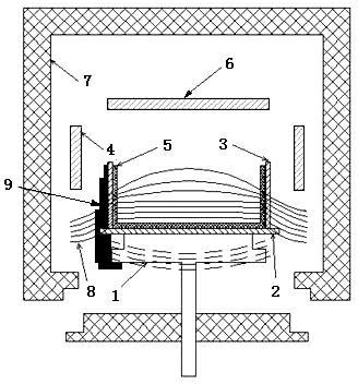
[0091] Such as image 3 As shown, the heat conduction block 1 is placed under the crucible bottom guard plate 2 (the bottom guard plate is generally made of graphite material), and the crucible bottom guard plate 2 is placed on the crucible 5 (generally a ceramic crucible); the four sides of the crucible 5 are set There are crucible side guards 3 (the side guards are generally made of graphite); a side heater 4 is arranged above the crucible 5 (the height of the crucible 5 is generally 400mm to 600mm, and can be increased if necessary). Top heater 6 is arranged on the top; Heat insulation cage 7 is arranged around side heater 4 and top heater 6, wherein the heat insulation cage 7 below is fixed, and the heat insulation cage 7 of surroundings is integrated above and can be promoted.

[0092] The surrounding insulation layer 9 (only one side of the insulation layer 9 is drawn for the sake of clarity in the illustration) is arranged outside the crucible side guard plate 3 of the ...

Embodiment 3

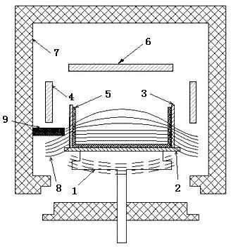
[0095] Such as Figure 4 As shown, the heat conduction block 1 is placed under the crucible bottom guard plate 2 (the bottom guard plate is generally made of graphite material), and the crucible bottom guard plate 2 is placed on the crucible 5 (generally a ceramic crucible); the four sides of the crucible 5 are set There are crucible side guards 3 (the side guards are generally made of graphite); a side heater 4 is arranged above the crucible 5 (the height of the crucible 5 is generally 400mm to 600mm, and can be increased if necessary). Top heater 6 is arranged on the top; Heat insulation cage 7 is arranged around side heater 4 and top heater 6, wherein the heat insulation cage 7 below is fixed, and the heat insulation cage 7 of surroundings is integrated above and can be promoted.

[0096] The surrounding insulation layer 9 (only one side of the insulation layer 9 is drawn for the sake of clarity in the illustration) is arranged outside the crucible side guard plate 3 of the...


PUM

PropertyMeasurementUnit
heightaaaaaaaaaa
thicknessaaaaaaaaaa
widthaaaaaaaaaa

Abstract

The invention discloses a method for producing similar mono-crystalline silicon by using a casting process. The method comprises the improvement on a GT (Gas Tight) furnace or ingot casting furnace equipment of heaters on the four surfaces and the top surface and the growth control of similar mono-crystal. The improvement of the ingot casting furnace equipment is that an improved similar mono-crystalline silicon ingot thermal field gradient device is provided. The growth control of the similar mono-crystal comprises one or a combination of a cast furnace silicon material and seed crystal placing method, a chemical material heating method and a method for stabilizing seed crystal at the bottom of a furnace after the seed crystal in the furnace is molten. The method disclosed by the invention has the benefits that: by changing a thermal field device and materials of the GT furnace or the heaters on the four surfaces and the top, completing the cast furnace silicon material and seed crystal placing method, the chemical material heating method and the method for stabilizing the seed crystal at the bottom of the furnace after the seed crystal in the furnace is molten, and the like, the internal temperature curve of the thermal field is changed, and a chemical material and growth isothermal curve can be obviously improved; furthermore, the seed crystal melting problem of the similar mono-crystal can be solved; and the problems of high cost, low reliability and low success rate of the similar mono-crystal production can be solved.

Description

technical field [0001] The invention relates to the technical field of crystal growth, and further relates to a method for producing similar single crystal silicon by casting. Background technique [0002] The methods of producing silicon ingots include: CZ method to produce monocrystalline silicon ingots, ingot casting method to produce polycrystalline silicon ingots, FZ method to produce monocrystalline silicon ingots, EFG to produce silicon ribbons and other methods. Due to cost issues, currently solar cells mainly use CZ method single crystal silicon wafers and casting method polycrystalline silicon wafers. The manufacturing cost of CZ monocrystalline silicon is 4 to 5 times that of ingot polysilicon, and the energy consumption is 5 to 7 times higher, resulting in less and less market share of CZ monocrystalline silicon. However, due to the production of polycrystalline silicon ingots by the ingot method, there are a large number of dislocations and grain boundaries, so...

Claims


Application Information

Patent Timeline
Patent Type & Authority Applications(China)
IPC IPC(8): C30B11/00
Inventor 石坚熊涛涛
Owner ANYANG PHOENIX PHOTOVOLTAIC TECH
Why Eureka
Try Eureka