Gradient improving device of thermal field for producing pseudo single crystal silicon ingot by casting method
A monocrystalline silicon ingot and casting method technology, which is applied in the field of thermal field devices and materials similar to single crystal silicon ingots produced by casting method, silicon ingot thermal field devices and materials, and can solve the problem of high cost of single crystal production and single crystal seed melting and other problems, to achieve the effect of reducing the height of the seed crystal, reducing the production cost, improving the chemical material and the growth isotherm curve
- Summary
- Abstract
- Description
- Claims
- Application Information
AI Technical Summary
Problems solved by technology
Method used
Image

Examples
Embodiment 1
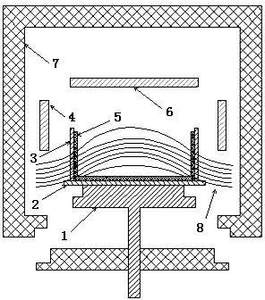
[0034] Such as figure 2 As shown, the heat conduction block 1 is placed under the crucible bottom guard plate 2 (the bottom guard plate is generally made of graphite material), and the crucible bottom guard plate 2 is placed on the crucible 5 (generally a ceramic crucible); the four sides of the crucible 5 are set There are crucible side guards 3 (the side guards are generally made of graphite); a side heater 4 is arranged above the crucible 5 (the height of the crucible 5 is generally 400mm to 600mm, and can be increased if necessary). Top heater 6 is arranged on the top; Heat insulation cage 7 is arranged around side heater 4 and top heater 6, wherein the heat insulation cage 7 below is fixed, and the heat insulation cage 7 of surroundings is integrated above and can be promoted.
[0035] The surrounding insulation layer 9 (for the sake of clarity in the illustration, only one side of the insulation layer 9 is drawn) is arranged on the outside of the crucible side guard pla...
Embodiment 2
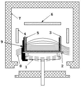
[0042] Such as image 3 As shown, the heat conduction block 1 is placed under the crucible bottom guard plate 2 (the bottom guard plate is generally made of graphite material), and the crucible bottom guard plate 2 is placed on the crucible 5 (generally a ceramic crucible); the four sides of the crucible 5 are set There are crucible side guards 3 (the side guards are generally made of graphite); a side heater 4 is arranged above the crucible 5 (the height of the crucible 5 is generally 400mm to 600mm, and can be increased if necessary). Top heater 6 is arranged on the top; Heat insulation cage 7 is arranged around side heater 4 and top heater 6, wherein the heat insulation cage 7 below is fixed, and the heat insulation cage 7 of surroundings is integrated above and can be promoted.
[0043] The surrounding insulation layer 9 (only one side of the insulation layer 9 is drawn for the sake of clarity in the illustration) is arranged outside the crucible side guard plate 3 of the ...
Embodiment 3
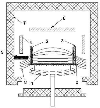
[0046] Such as Figure 4 As shown, the heat conduction block 1 is placed under the crucible bottom guard plate 2 (the bottom guard plate is generally made of graphite material), and the crucible bottom guard plate 2 is placed on the crucible 5 (generally a ceramic crucible); the four sides of the crucible 5 are set There are crucible side guards 3 (the side guards are generally made of graphite); a side heater 4 is arranged above the crucible 5 (the height of the crucible 5 is generally 400mm to 600mm, and can be increased if necessary). Top heater 6 is arranged on the top; Heat insulation cage 7 is arranged around side heater 4 and top heater 6, wherein the heat insulation cage 7 below is fixed, and the heat insulation cage 7 of surroundings is integrated above and can be promoted.
[0047] The surrounding insulation layer 9 (only one side of the insulation layer 9 is drawn for the sake of clarity in the illustration) is arranged outside the crucible side guard plate 3 of the...
PUM
| Property | Measurement | Unit |
|---|---|---|
| height | aaaaa | aaaaa |
| thickness | aaaaa | aaaaa |
| width | aaaaa | aaaaa |
Abstract
Description
Claims
Application Information
 - R&D
- Intellectual Property
- Life Sciences
- Materials
- Tech Scout
- Unparalleled Data Quality
- Higher Quality Content
- 60% Fewer Hallucinations
Browse by: Latest US Patents, China's latest patents, Technical Efficacy Thesaurus, Application Domain, Technology Topic, Popular Technical Reports.
© 2025 PatSnap. All rights reserved.Legal|Privacy policy|Modern Slavery Act Transparency Statement|Sitemap|About US| Contact US: help@patsnap.com