Supercharge Your Innovation With Domain-Expert AI Agents!

Damping valve device with a multi-stage damping characteristic curve

A damping valve, damping medium technology, applied in the direction of shock absorbers, shock absorbers, springs/shock absorbers, etc.

Inactive Publication Date: 2011-11-16
ZF FRIEDRICHSHAFEN AG
View PDF6 Cites 3 Cited by
  • Summary
  • Abstract
  • Description
  • Claims
  • Application Information

AI Technical Summary

Problems solved by technology

It is difficult to solve this contradiction with conventional damping valves

Method used


Image

  • Damping valve device with a multi-stage damping characteristic curve
  • Damping valve device with a multi-stage damping characteristic curve
  • Damping valve device with a multi-stage damping characteristic curve

Examples


Embodiment Construction

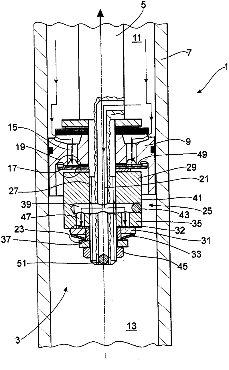
[0019] figure 1 A portion of the shock absorber 1 is shown in the region of the damping valve arrangement 3 , which is arranged in the cylinder 7 on the piston rod 5 as a carrier. The piston 9 as first damping valve body and part of the damping valve arrangement 3 divides the cylinder 7 into a piston rod-side working chamber 11 and a piston rod-distant working chamber 13 . In the piston 9, at least one throughflow channel 15 is arranged in each flow direction of the damping medium in the cylinder 7, the outlet of which is at least partly covered by at least one valve disk 17, thereby forming a first Damping valve 19. In this specific embodiment, two through-flow channels are shown for the through-flow during the extension movement of the piston rod 5 . The flow channel provided for the sliding movement is formed in another section of the piston 9 and is therefore not visible.

[0020] A flow channel 21 in the piston rod 5 is connected to the piston rod-side working chamber...


PUM


Abstract

The present invention relates to a damping valve device with a multi-stage damping characteristic curve. A damping valve for a vibration damper comprises a first damping valve and a second damping valve, at least two hydraulic flowing channels in parallel connection are provided for one flowing direction of a damping medium, wherein the cross sections the outlets of at least two flowing channels are respectively affected by at least one valve disc, thus obtaining the first damping valve and the second damping valve. The two damping valves are fixed on one support, one flowing channel is disposed on the support, the first damping valve is fixed on the support through a fastening member, the fastening member forms the damping valve casing of the second damping valve, at least one valve disc of the second damping valve is fixed with the first damping valve through an independent fastening member regardless of the attachment of the first damping valve, and the damping valve casing of the second damping valve is designed to be a single member.

Description

technical field [0001] The invention relates to a damping valve arrangement with a multi-stage damping force characteristic curve according to the preamble of claim 1 . Background technique [0002] In the case of shock absorbers with conventional damping valve arrangements, ie, which cannot be adjusted arbitrarily via the actuator, the adjustment of the damping force characteristic curve always results in a compromise. On the one hand, driving safety must be ensured, for which a large damping force is appropriate; on the other hand, comfort requirements must be met. It is difficult to resolve this contradiction with conventional damping valves. [0003] DE 2022021 A1 discloses a shock absorber with a damping valve arrangement whose damping force characteristic curve has at least four damping force characteristic curve regions ( FIG. 9 ). For this purpose, two damping valves connected in parallel are used, by means of which different opening characteristics and in the maxi...

Claims


Application Information

Patent Timeline
IPC IPC(8): F16F9/34
CPCF16F9/516F16F9/348
Inventor H・布劳恩罗伊特R・莫勒
Owner ZF FRIEDRICHSHAFEN AG
Features
  • R&D
  • Intellectual Property
  • Life Sciences
  • Materials
  • Tech Scout
  • Unparalleled Data Quality
  • Higher Quality Content
  • 60% Fewer Hallucinations
Learn More