Multi-level converter with DC (direct current) capacitor assisted voltage-sharing circuit

A voltage equalizing circuit and DC capacitor technology, applied in the direction of output power conversion device, AC power input conversion to DC power output, electrical components, etc., can solve the problems of limiting the application of multi-level conversion circuits, etc., and achieve simple control strategies, The effect of low hardware and software requirements and low inductance

Inactive Publication Date: 2011-11-16
SOUTHWEST JIAOTONG UNIV
View PDF5 Cites 16 Cited by
  • Summary
  • Abstract
  • Description
  • Claims
  • Application Information

AI Technical Summary

Problems solved by technology

For example, when the multilevel converter transmits pure active current, that is, when the load current angle is near 0 degrees, in order to ensure the stability of the DC voltage, the PWM modulation depth is required to be the highest and less than about 55%, which greatly limits the multilevel conversion Application of Circuits in the Field of Active Power Transfer

Method used


Image

  • Multi-level converter with DC (direct current) capacitor assisted voltage-sharing circuit
  • Multi-level converter with DC (direct current) capacitor assisted voltage-sharing circuit
  • Multi-level converter with DC (direct current) capacitor assisted voltage-sharing circuit

Examples


Embodiment 1

[0038] Embodiment 1 - two-stage auxiliary voltage equalization circuit

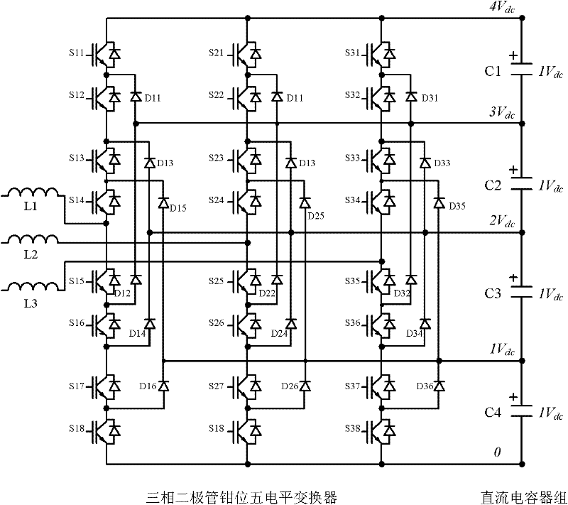
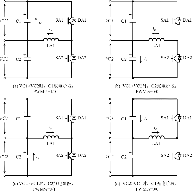
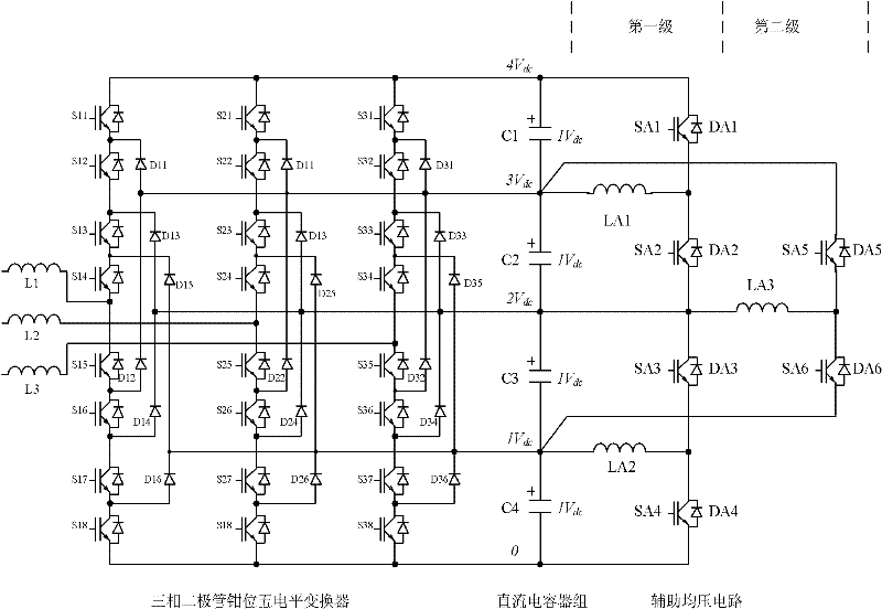
[0039] image 3 A two-stage auxiliary voltage equalizing circuit is provided by taking the five-level diode clamp main circuit as an example. The circuit uses 3 sets of figure 2 The basic circuit of the voltage sharing inductor is shown.

[0040]The first-stage voltage equalizing circuit includes: the switch devices SA1 and SA2 of the first group of inductive voltage equalizing basic circuits are connected in parallel with capacitors C1 and C2, and the middle connection point of the two is connected together through the inductor LA1 to realize the voltage equalization of C1 and C2 ; Switching devices SA3 and SA4 of the second group of inductive voltage equalization basic circuit are connected in parallel with capacitors C3 and C4, and the middle connection point of the two is connected together through inductance LA2 to realize voltage equalization of C3 and C4.

[0041] The second-stage voltage equal...

Embodiment 2

[0044] Embodiment 2——A single-inductance auxiliary voltage equalization circuit suitable for five-level numbers

[0045] Figure 5 It is a voltage equalizing circuit for all five-level DC capacitor voltages realized by a single inductor. This circuit will image 3 The two-stage multi-group independent voltage equalizing basic circuit is simplified into a group of single inductor voltage equalizing circuits, which respectively construct charging and discharging paths of DC capacitors C1-C4 for one inductor. That is, through SA1, SA7, LA1, DA16, SA2, DA10 in series to form the discharge circuit of capacitor C1, through DA9, SA7, LA1, DA16, DA13 in series to form the charging circuit of capacitor C1; through DA9, SA7, LA1, DA16, SA3 in series Form the discharge circuit of capacitor C2, form the charging circuit of capacitor C2 through SA4, DA15, LA1, DA16, SA2, DA10 in series; form the discharge circuit of capacitor C3 through SA4, DA15, LA1, SA8, DA12 in series, through SA5, DA...


PUM


Abstract

The invention discloses a multi-level converter with a DC (direct current) capacitor assisted voltage-sharing circuit. The voltage-sharing circuit comprises a primary voltage-sharing circuit and a secondary voltage-sharing circuit; for the multi-level converter with N+1 levels and N DC capacitors, the primary voltage-sharing circuit comprises N/2 inductance voltage-sharing basic circuits; a switching element SA1n and a switching element SA1 (n-1) are connected with a capacitor Cn and a capacitor C (n-1) in parallel and the central connection points between the switching elements and the capacitors are connected by an inductor LA1(n/2), thus realizing the voltage-sharing of the capacitor Cn and the capacitor C (n-1); the secondary voltage-sharing circuit comprises N/2-1 groups of inductance voltage-sharing basic circuits to realize the voltage-sharing of the capacitor C (n-1) and a capacitor C (n-2); and finally, the N DC capacitors C realize the equalization of all voltages. The multi-level converter is suitable for the voltage-sharing of any level, does not influence an existing main circuit and a control principle and ensures that a main circuit converter can realize power transmission of any power factor under the condition of any modulation depth. The invention also provides specific circuits of a five-level converter as well as a realization circuit for minimizing the number of the inductors and a control method thereof.

Description

technical field [0001] The invention relates to power control equipment, in particular to a voltage equalization control circuit and a control method for a DC capacitor voltage of a multilevel converter based on power electronic technology. Background technique [0002] In the application of multilevel converters, multiple DC capacitors are usually used in series to provide higher DC voltage, and the DC voltage is divided into multiple levels to provide stable and balanced DC voltage for the normal operation of the multilevel converter. Taking the diode clamping circuit as an example, multiple series switching devices of each bridge arm of the converter are connected to a certain DC capacitor through a diode, that is, the voltage of the switching device is clamped to the voltage of a connected DC capacitor through the diode, and the The DC bus voltage is divided into several levels. Therefore, the multiple switching devices of each bridge arm can output voltage signals of d...

Claims


Application Information

Patent Timeline
Patent Type & Authority Applications(China)
IPC IPC(8): H02M7/487
Inventor 舒泽亮
Owner SOUTHWEST JIAOTONG UNIV
Why Eureka
Try Eureka