Drive train for a motor vehicle

A technology of power train and vehicle, applied in the field of power train, can solve problems such as the influence of the actual power of the motor, and achieve the effect of improving the service life and reducing the mechanical load

Inactive Publication Date: 2011-11-16
ZF FRIEDRICHSHAFEN AG
View PDF8 Cites 5 Cited by
  • Summary
  • Abstract
  • Description
  • Claims
  • Application Information

AI Technical Summary

Problems solved by technology

As a result, the vibrations known to be generated by such drive motors are transmitted directly to the electric machine, whereby vibrations can arise in the alignment of the rotor relative to the stator, which have a negative effect on the actual power of the electric machine

Method used


Image

  • Drive train for a motor vehicle
  • Drive train for a motor vehicle
  • Drive train for a motor vehicle

Examples


Embodiment Construction

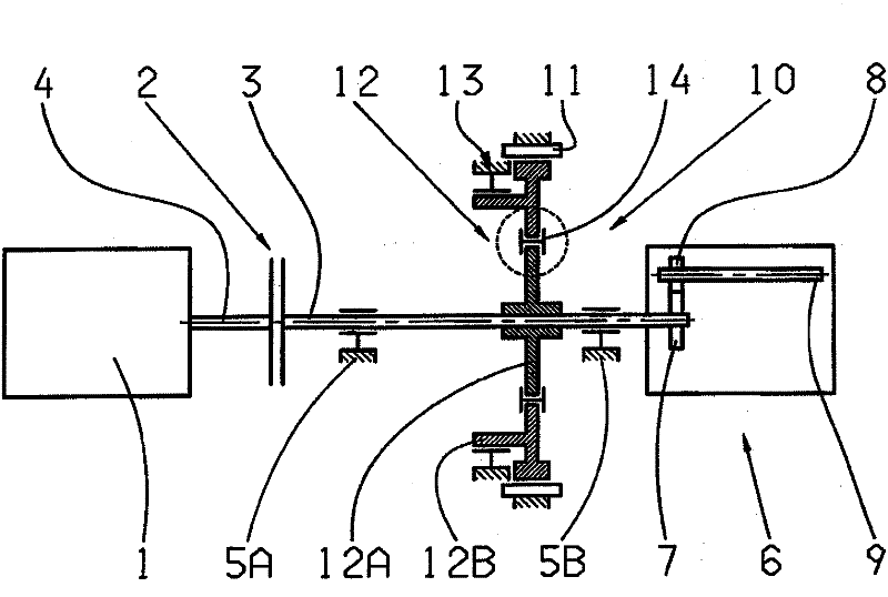
[0022] exist figure 1 shows that the drive motor 1 is coupled to the drive shaft 3 via a clutch 2 serving as a friction-locking (reibschlüssig) starting clutch. Thus, in the engaged state of the clutch 2 , the torque generated by the drive motor 1 is transmitted from the motor output shaft 4 via the clutch 2 to the drive shaft 3 of the drive train. Conversely, in the engaged state, no torque is transmitted from the drive motor 1 to the drive shaft 3 via the clutch 2 . The drive shaft 3 is rotatably supported by two shaft bearings 5A, 5B fastened to the housing and serves as an input shaft for a transmission 6 of the countershaft transmission type, for which purpose a resistive A gear 7 is arranged in a rotationally opposite manner, which transmits the torque from the drive shaft 3 to the gear 8 of the intermediate shaft 9 of the transmission 6 .

[0023] Arranged around the drive shaft 3 is an electric motor 10 equipped with a stator 11 affixed to the housing and a two-part ...


PUM


Abstract

The invention relates to a drive train for a motor vehicle, comprising at least a rotatable drive shaft (3) and an electric motor (10) that has a stator (11) fixed to the housing and a rotor (12) that can rotate such that it is coupled to the drive shaft (3), characterized in that the rotor (12) is configured in at least two parts, the first rotor part (12A) being directly coupled to the drive shaft (3) and the second rotor part (12B) being directly drivable with the stator (11), and wherein the first rotor part (12A) and the second rotor part (12B) are coupled to each other in such a manner that torque can be transmitted and that both can be tilted in relation to each other. According to the invention, the second rotor part (12B) is rotatably supported by a rotor bearing (13) fixed to the housing and is aligned with respect to the stator (11).

Description

technical field [0001] The invention relates to a drive train for a vehicle, which is formed at least from a rotatable drive shaft and an electric machine. In this case, the electric machine comprises a stator fastened to the housing and a rotor designed in at least two parts, wherein a first rotor part is directly coupled to the drive shaft and a second rotor part can be directly driven by means of the stator. In this case, the first rotor part and the second rotor part are coupled in a torque-transmissible and tiltable manner relative to one another. Background technique [0002] A drive train with a two-part rotor is known from DE 196 31 384 C1, in which a vibration isolator is arranged between the rotor parts, which prevents the further transmission of torsional vibrations arising from the input side onto the driven side. Furthermore, the drive train is equipped with an internal combustion engine-operated drive motor, the crankshaft of which is directly connected via a...

Claims


Application Information

Patent Timeline
Patent Type & Authority Applications(China)
IPC IPC(8): B60K1/02B60K6/26B60K17/22H02K7/00F02N11/04F16F15/12F02N15/06F16F15/14B60L50/16
CPCH02K5/24H02K7/003Y02T10/7258H02K7/006H02K1/30F16F15/1201F02N11/00B60K6/26B60K1/02Y02T10/72
Inventor 雷克·霍夫曼奥利弗·舍尔沃尔夫冈·伊尔巴赫尔马丁·拉姆克托马斯·格南特
Owner ZF FRIEDRICHSHAFEN AG
Why Eureka
Try Eureka