Spring brake cylinder with external bleeding

A technology of energy storage brake and brake cylinder, which is applied in the direction of brakes, brake cylinders, brake components, etc., and can solve the problem that the exhaust valve is not enough to keep the exhaust valve closed.

Active Publication Date: 2011-11-16
KNORR-BREMSE SYST FUER NUTZFAHRZEUGE GMBH
View PDF8 Cites 0 Cited by
  • Summary
  • Abstract
  • Description
  • Claims
  • Application Information

AI Technical Summary

Problems solved by technology

However, if the operating brake pressure and/or the operating brake pressure gradient are below a certain threshold based on a correspondingly lower operating brak

Method used


Image

  • Spring brake cylinder with external bleeding
  • Spring brake cylinder with external bleeding
  • Spring brake cylinder with external bleeding

Examples


Embodiment Construction

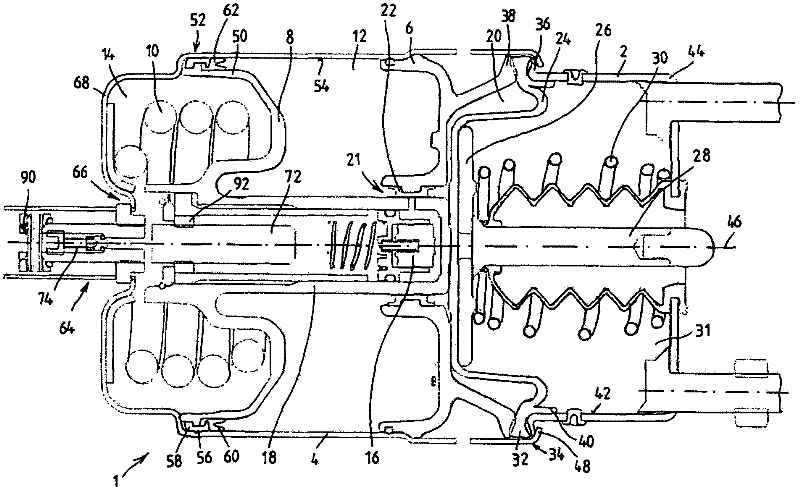
[0022] figure 1 A combined operating brake cylinder and spring-loaded brake cylinder 1 is shown in , hereinafter referred to as combined cylinder. The combined cylinder 1 is composed of a running brake cylinder 2 and a spring energy storage brake cylinder 4 which is structurally and functionally connected with it. The running brake cylinder 2 and the spring-loaded brake cylinder 4 are separated from each other by a partition wall 6 . A spring storage brake piston 8 is displaceably arranged inside the spring storage brake cylinder 4 , wherein a storage spring 10 bears against one side of the spring storage brake piston 8 . The storage spring 10 is supported on its opposite side on the underside of the spring storage brake cylinder 4 . A spring storage brake chamber 12 is designed between the spring storage brake piston 8 and the partition wall 6, which is connected to a pressure regulation module (not shown for reasons of size) for its control. Inflate and deflate. During c...


PUM


Abstract

The invention relates to a spring brake cylinder (1) for vehicle brake systems, comprising a spring brake piston (8) that is located in a spring brake cylinder (4) and can be actuated by at least one accumulator spring (10), said piston separating a spring chamber (14) that houses the accumulator spring (10) from a spring brake chamber (12) of the spring brake cylinder (4) that can be aerated andbled, and comprising a release unit (64) for the manual release of the spring brake or a release actuated by a drive unit. The release unit (64) contains a release spindle (72) that co-operates with a spring brake piston rod (18) of the spring brake piston (8), is held in an opening (66) of the spring brake cylinder (4) and can be actuated from outside the spring brake cylinder (4). According to the invention, a flow connection (82) containing a valve unit (74) is provided in the release spindle (72), between the spring chamber (14) and the environment, said valve unit (74) opening and blocking the flow connection (82) depending on the pressure that prevails in the spring chamber (14).

Description

technical field [0001] The invention relates to a spring accumulator brake cylinder for a braking system of a vehicle according to the preamble of claim 1 , which has a spring accumulator brake cylinder arranged in the spring accumulator brake cylinder , a spring-charged brake piston actuatable by at least one stored-energy spring, the spring-charged brake piston accommodating the spring chamber of the stored-energy spring and the inflatable and deflatable spring-charged brake cylinder of the spring-charged brake cylinder The energy brake chamber is separated; and the release device is used to release the spring energy storage brake manually or through the operation of the transmission, wherein the release device includes the spring energy storage brake piston rod and the spring energy storage brake piston Cooperating and held in the opening of the spring-loaded brake cylinder, release spindles actuatable from the outside of the spring-loaded brake cylinder. Background techn...

Claims


Application Information

Patent Timeline
IPC IPC(8): B60T17/08F16D65/14F16D65/28
CPCB60T17/083F16D2123/00F16D2121/02F16D65/28F16D2127/04F16D2121/12
Inventor 西尔万・德劳奥尔特文森特・马丁弗兰克・瓦赞
Owner KNORR-BREMSE SYST FUER NUTZFAHRZEUGE GMBH
Why Eureka
Try Eureka