
Electrode for generation of hydrogen

a technology of electrolysis and electrolysis chamber, which is applied in the direction of electrolysis coating, transportation and packaging, multiple component coating, etc., can solve the problems of short operating life of electrolysis chamber, and achieve the effects of stable quality, excellent durability, and low overvoltag

Inactive Publication Date: 2006-10-17
ASAHI KASEI KK
View PDF22 Cites 11 Cited by
  • Summary
  • Abstract
  • Description
  • Claims
  • Application Information

AI Technical Summary

Benefits of technology

The present invention provides a stable and durable cathode for hydrogen generation that is low in overvoltage and excellent in quality. The invention solves the problems of previous methods by using a pyrolysis method that is suitable for mass production. The invention also takes advantage of the fact that ruthenium oxide and ruthenium hydrate are effective electrode materials, but they are unstable at high hydrogen generation potential. The invention proposes a coating layer that is stable even in an oxidative atmosphere with generation of reductive hydrogen, and can prevent the physical exfoliation of the coating layer. The invention also takes into account the fact that certain compounds, such as lanthanum, cerium, and yttrium, are poor in hydrogen generation activity, but can maintain a low overvoltage over a long period of time. The invention provides a method for producing the electrode that allows for the application of a mixture of a platinum group compound and a compound selected from the group consisting of a lanthanum, cerium, and yttrium in a ratio of 1 / 20 to ½ mol in relation to one mol of metal component in the platinum group compound, and an organic acid in a ratio of 1 / 20 to 2 mol in relation to one mol of metal component in the platinum group compound. The invention also provides an electrode that is stable, low in overvoltage, and can maintain a low overvoltage over a long period of time.

Problems solved by technology

However, even in the above described examples, the electrode operating life is short so that as matters stand, indeed, further elongation of the electrode operating life is an objective.

Method used


Image

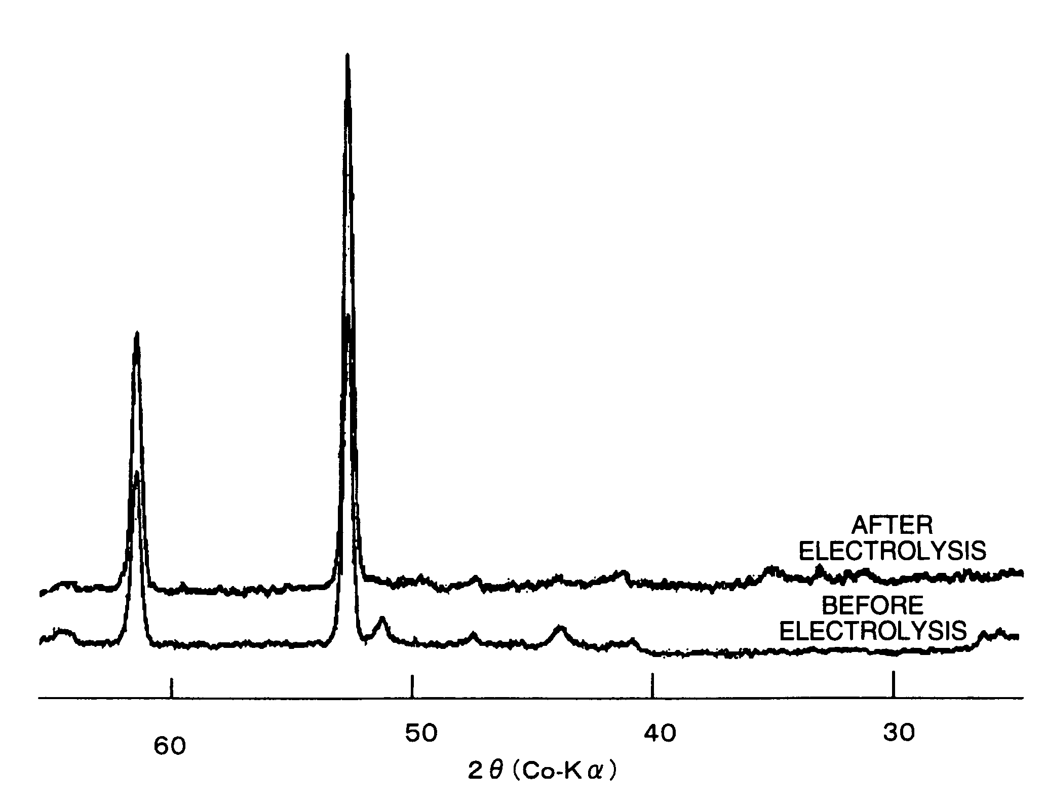
  • Electrode for generation of hydrogen
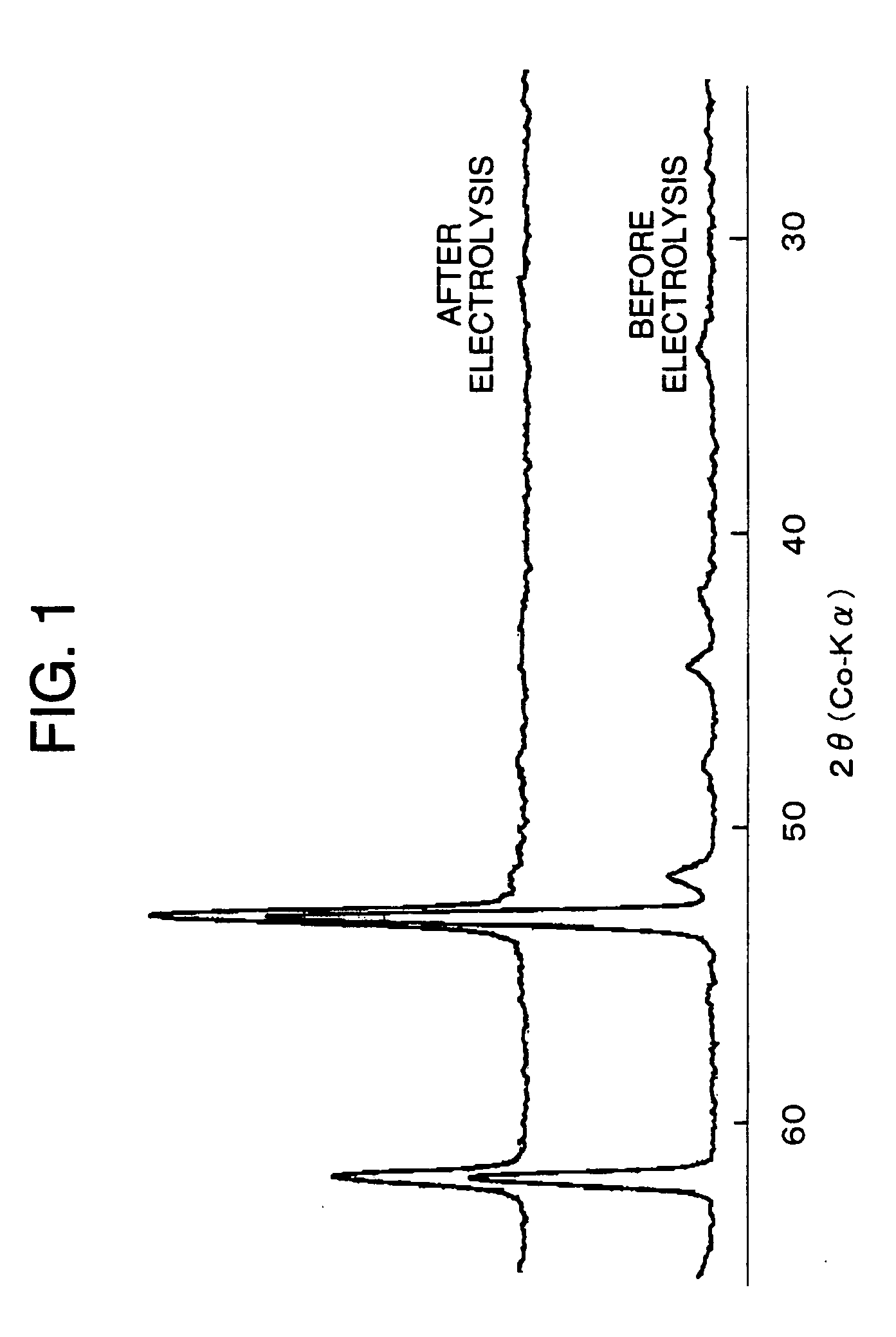
  • Electrode for generation of hydrogen
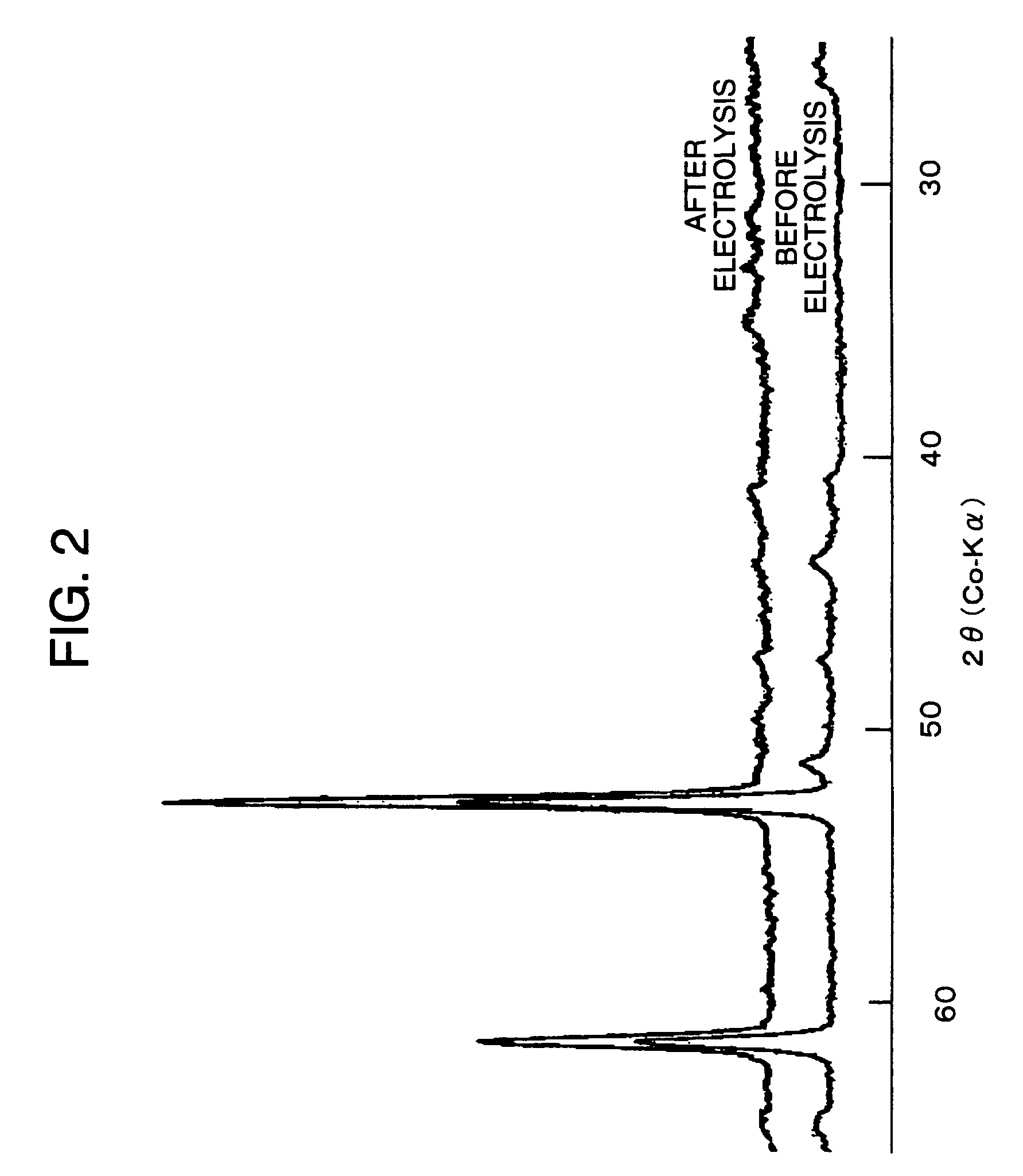
  • Electrode for generation of hydrogen

Examples


example 1

[0073]An electrode-shaped nickel expanded base, in which the short way of aperture dimension SW was 3 mm, the long way of aperture dimension LW was 4.5 mm, the feed pitch for expansion processing was 0.7 mm, and the plate thickness was 0.7 mm, was calcined at 400° C. for 3 hours in the air and an oxide coating layer was thereby formed on the surface thereof. Subsequently, blasting with an alumina powder of 100 μm or less in weight average particle size was conducted to provide the base surface with irregularities. Then, the base was subjected to acid treatment in 25 wt % sulfuric acid at 90° C. for 4 hours, and the base surface was provided with finer irregularities.

[0074]In the next place, the nickel base was soaked into a solution in which a surfactant “Nonion N210” (trade mark: a nonionic surfactant manufactured by NOF Corp. (Nippon Yushi K.K.)) was dissolved in water in the ratio of 0.15 g of the surfactant to 200 g of water, and then the base was taken out and dried in the air....

examples 2 to 6

[0084]An electrode-shaped nickel expanded base, in which the short way of aperture dimension SW was 3 mm, the long way of aperture dimension LW was 4.5 mm, the feed pitch for expansion processing was 0.7 mm, and the plate thickness was 0.7 mm, was calcined in the air at 400° C. for 3 hours and an oxide coating layer was thereby formed on the surface thereof. Subsequently, blasting with an alumina powder of 100 μm or less in weight average particle size was conducted to provide the base surface with irregularities. Then, the base was subjected to acid treatment in 25 wt % sulfuric acid at 90° C. for 4 hours, and the base surface was provided with finer irregularities.

[0085]In the next place, the nickel base was soaked into a solution in which a surfactant “Nonion N210” (trade mark: a nonionic surfactant manufactured by NOF Corp. (Nippon Yushi K.K.)) was dissolved in water in the ratio of 0.15 g of the surfactant to 200 g of water, and then the base was taken out and dried in the air....

example 7

[0098]A woven mesh base made of a thin nickel wire of 0.15 mm in diameter with a mesh 50 aperture was calcined at 400° C. for 3 hours in the air to form an oxide coating layer on the surface thereof. Subsequently, blasting with an alumina powder of 100 μm or less in weight average particle size was conducted to provide the base surface with irregularities. Then, the base was subjected to acid treatment in 25 wt % sulfuric acid at 90° C. for 4 hours, and the base surface was provided with finer irregularities.

[0099]In the next place, the nickel base was soaked into a solution in which a surfactant “Nonion N210” (trade mark: a nonionic surfactant manufactured by NOF Corp. (Nippon Yoshi K.K.)) was dissolved in water in the ratio of 0.15 g of the surfactant to 200 g of water, and then the base was taken out and dried in the air.

[0100]Then, oxalic acid dihydrate was added to a ruthenium chloride solution in hydrochloric acid with a metal concentration of 100 g / L in such a way that the am...


PUM

PropertyMeasurementUnit
overvoltageaaaaaaaaaa
overvoltagesaaaaaaaaaa
Raaaaaaaaaaa

Abstract

An electrode for use in hydrogen generation comprising a conductive base and a coating layer formed thereon of a composition obtainable by thermally decomposing, in the presence of an organic acid, a mixture comprising at least one type of platinum compound.

Description

[0001]This application is the national phase under 35 U.S.C. § 371 of PCT International Application No. PCT / JP03 / 03423 which has an International filing date of Mar. 20, 2003, which designated the United States of America.TECHNICAL FIELD[0002]The present invention relates to an electrode for use in electrolysis, in particular, an electrode for use in hydrogen generation which is suitably used in the electrolysis of sodium chloride based on an ion exchange membrane method and which exhibits a low overvoltage over a long period of time.BACKGROUND ART[0003]In the process of the electrolysis of sodium chloride based on an ion exchange membrane method, the reduction of energy consumption is one of the most important issues. A detailed analysis of the voltage involved in the electrolysis of sodium chloride based on an ion exchange membrane method shows that the voltage includes, in addition to the theoretically required voltage, the voltage due to the ion exchange membrane, the overvoltag...

Claims


Application Information

Patent Timeline
Patent Type & Authority Patents(United States)
IPC IPC(8): B05D3/02B05D5/12C25B11/04C25B11/052
CPCC25B11/0473C25B11/0478C25B11/0484Y10T428/254Y02E60/366Y02E60/36C25B11/081C25B11/093C25B11/091C25B11/052C25B9/23
Inventor HOUDA, HIROYOSHINOAKI, YASUHIDESAKO, KENTARO
Owner ASAHI KASEI KK
Learn More