EGR device for internal combustion engine

An internal combustion engine, EGR valve technology, applied in the direction of internal combustion piston engine, combustion engine, mechanical equipment, etc., can solve the problems of slow response of EGR gas, inability to recognize the response of EGR gas, slowness, etc.

Inactive Publication Date: 2014-03-05
HINO MOTORS LTD
View PDF5 Cites 0 Cited by
  • Summary
  • Abstract
  • Description
  • Claims
  • Application Information

AI Technical Summary

Problems solved by technology

[0010] However, when the control device 22 issues the opening degree command signal 18a to the actuator 18 of the EGR valve 19 based on the target EGR rate, a response of EGR gas occurs when the EGR valve 19 is slowly opened and closed due to the sticking of the EGR valve 19 or the like. On the other hand, the EGR valve 19 is judged to be normal based on the EGR valve 19 reaching the target opening, so there is a problem that it is impossible to recognize the slow response of the EGR gas.

Method used


Image

  • EGR device for internal combustion engine
  • EGR device for internal combustion engine
  • EGR device for internal combustion engine

Examples


Embodiment Construction

[0024] Hereinafter, embodiments of the present invention will be described with reference to the drawings.

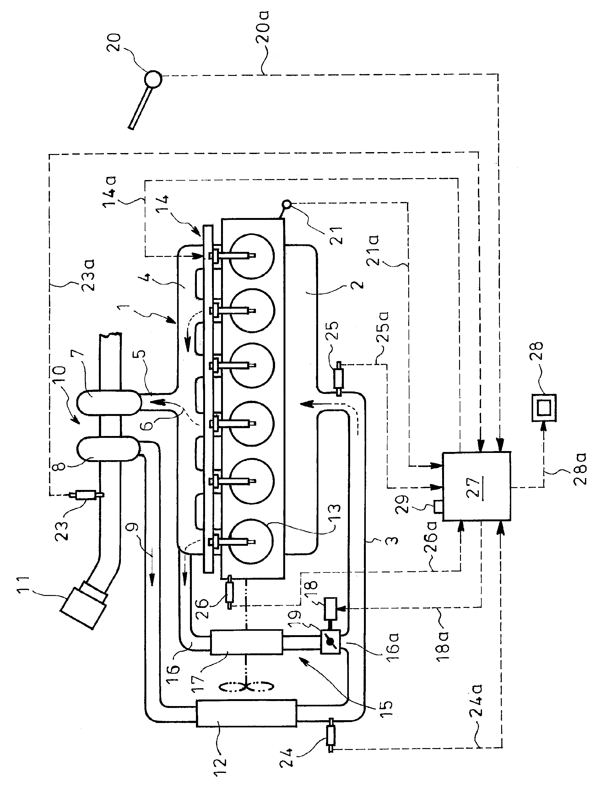
[0025] Figure 2 ~ Figure 4 Indicates an embodiment of the present invention, in the figure, marked with figure 1 Parts with the same symbols represent the same thing.

[0026] In the EGR device for an internal combustion engine shown in the embodiment, an EGR mechanism 15 is provided between the air supply passage 3 and the exhaust passage 5 to return EGR gas from the exhaust passage 5 of the engine 1 to the air supply passage 3 . In the EGR mechanism 15, the air supply passage 3 is connected between the intake manifold 2 and the exhaust manifold 4 through the EGR pipe 16. The EGR pipe 16 of the EGR mechanism 15 has an EGR cooler 17, and is provided with actuated The EGR valve 19 is opened and closed by the valve 18.

[0027] On the upstream side of the compressor 8 , there is an air flow sensor (AFM: Air Flow Meter) 23 that detects the amount of air sucked into the...


PUM


Abstract

An EGR device for an internal combustion engine has an EGR means to return an EGR gas from an exhaust passage to an intake passage of an engine. The EGR device is configured to determine a target EGR ratio from an engine rotation number and an engine load and calculate an estimate EGR ratio from an intake air amount to the engine and a cylinder intake gas amount to detect a response delay of the EGR gas from a difference between the target and estimate EGR ratios.

Description

technical field [0001] The present invention relates to an EGR device of an internal combustion engine which supplies EGR gas to effectively reduce the generation of NOx. Background technique [0002] In the past, exhaust gas recirculation devices (EGR devices) have been widely used in internal combustion engines, which allow part of the exhaust gas (hereinafter referred to as "EGR gas") to return to the air supply system to slow down combustion and reduce the combustion speed to achieve NOx decrease. [0003] figure 1 It is a diagram showing an example of an internal combustion engine with a supercharger, which has an air supply passage 3 connected to an intake manifold 2 of the engine 1 and an exhaust passage 5 connected to an exhaust manifold 4 . The exhaust passage 5 has a turbine 7 driven by the exhaust gas 6, and the air supply passage 3 is provided with a compressor 8 that generates compressed air 9 through the turbine 7. The turbine 7 and the compressor 8 constitut...

Claims


Application Information

Patent Timeline
Patent Type & Authority Patents(China)
IPC IPC(8): F02M25/07
CPCF02M25/0707F02D41/0072F02M25/0754F02B29/0425F02D2041/1431F02M25/0702Y02T10/47Y02T10/144F02D23/02F02M25/073F02D21/08F02M26/05F02M26/27F02M26/47F02M26/49Y02T10/12Y02T10/40
Inventor 名越胜之
Owner HINO MOTORS LTD
Why Eureka
Try Eureka