Structured electrode for ceramic sensor elements

A technology of sensor element and structured part, applied in the field of known sensor element

Active Publication Date: 2011-11-16
ROBERT BOSCH GMBH
View PDF4 Cites 5 Cited by
  • Summary
  • Abstract
  • Description
  • Claims
  • Application Information

AI Technical Summary

Problems solved by technology

[0005] However, the electrode structure in known sensor elements, for example

Method used


Image

  • Structured electrode for ceramic sensor elements
  • Structured electrode for ceramic sensor elements
  • Structured electrode for ceramic sensor elements

Examples


Embodiment Construction

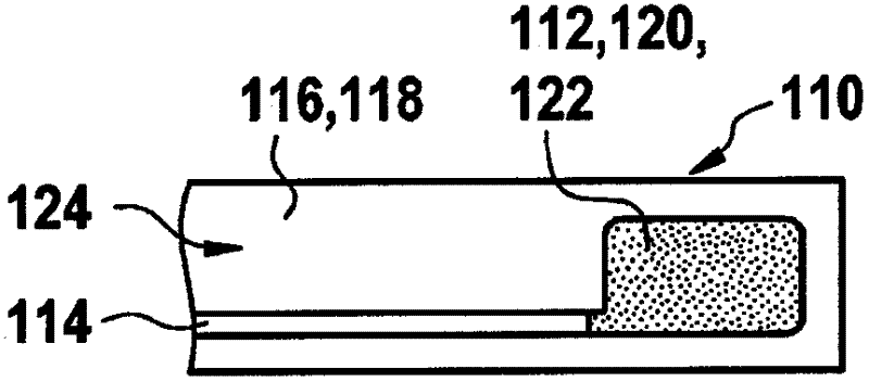
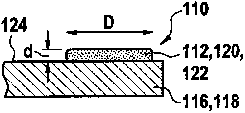
[0050] exist Figure 1A and 1B An example of a conventional sensor element 110 is schematically shown in . Only one electrode 112 of the sensor element 110 and the lead 114 leading to this electrode 112 are shown here (only in the Figure 1A visible in). here Figure 1A Electrode 112 and sensor element 110 are shown in top view, while Figure 1B A sectional view of sensor element 110 is shown from the side.

[0051] Electrode 112 is coated on solid electrolyte layer 116 which includes solid electrolyte material 118 . For example, the solid electrolyte material may be yttrium stabilized zirconia (YSZ), where typically 5.5 mole percent of YSZ is used. Electrode 112 is applied to solid electrolyte layer 116 , which may be formed, for example, as a thin-film layer. Electrode 112 is designed, for example, as a platinum-YSZ cermet electrode and generally has a porous structure. For the manufacture of such electrodes 112 typically an electrode paste is used which has a metallic ...


PUM


Abstract

The invention relates to a sensor element (110), particularly for capturing a property of a gas in a measuring gas space. The sensor element (110) comprises at least one solid electrolyte layer (116) having at least one ceramic solid electrolyte material (118) and at least one electrode (112) contacting the solid electrolyte layer (116) directly or indirectly. The electrode (112) comprises at least one ceramic material (122) and at least one metal material (120). The electrode (112) has a lateral extension and has structuring (126, 140) extending parallel and/or perpendicular to the lateral extension within the lateral extension. The structuring (126, 140) is designed to enlarge an electrode surface of the electrode (112).

Description

Background technique [0001] The present invention relates to known sensor elements which are based on the electrolytic properties of a specific solid, ie the ability of the solid to conduct specific ions. Such sensor elements are used in various fields of natural science and technology, wherein the invention described below is not restricted to a specific field of application. However, such sensor elements can be used in particular in the field of exhaust gas analysis, for example in motor vehicles, stationary engines or combustion systems. For example, such sensor elements can be used in motor vehicles to measure the air-fuel mixture composition. Such sensor elements are used in particular in so-called oxygen sensors / lambda sensors and play an important role in the reduction of pollutants in the exhaust gas both in Otto engines and in diesel technology. As an example of a possible configuration of such a sensor element, reference may be made to Robert Bosch GmbH: "Sensoren ...

Claims


Application Information

Patent Timeline
IPC IPC(8): G01N27/407
CPCG01N27/4075
Inventor H-J・伦茨J・施奈德
Owner ROBERT BOSCH GMBH
Why Eureka
Try Eureka