Pressurized endosseous implant prosthesis

A technology for implants and prostheses, applied in the field of biomedical engineering, can solve problems such as bone resorption failure, and achieve the effect of improving long-term stability and practicability

Inactive Publication Date: 2011-11-23
FOURTH MILITARY MEDICAL UNIVERSITY
View PDF5 Cites 3 Cited by
  • Summary
  • Abstract
  • Description
  • Claims
  • Application Information

AI Technical Summary

Problems solved by technology

The pressurized intraosseous implant can well solve the problem of failure caused by bone resorption caused by the stress shielding effect during the long-term use of the implant

Method used


Image

  • Pressurized endosseous implant prosthesis
  • Pressurized endosseous implant prosthesis
  • Pressurized endosseous implant prosthesis

Examples


Embodiment Construction

[0013] The present invention will be further described in detail below in conjunction with the drawings.

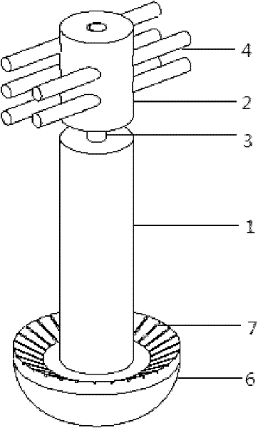
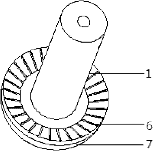
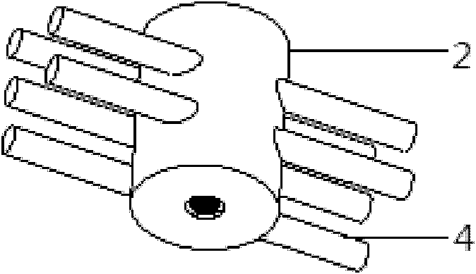
[0014] See figure 1 , 2 , 3, 4, the present invention includes an anchor (composed of intramedullary fixation 2 and cortical nail 4), a compression traction rod (composed of traction rod 3 and disc spring 5), and intramedullary body 1 connected in sequence. Among them, the cylindrical intramedullary fixation member 2 with five parallel staggered holes on the side is fixed in the femoral medullary cavity by means of cortical nails 4 penetrating the cortical bone on both sides. The lower end of the intramedullary body 1 is a mushroom-shaped structure 6, and the intramedullary body 1 is a hollow structure with internal threads. The upper hollow cavity of the intramedullary body 1 is provided with a drawbar 3 with a disc spring 5, and the drawbar 3 extends One end of the intramedullary body 1 is connected with the intramedullary fixing member 2 through a screw thread, and the si...


PUM


Abstract

The invention discloses a pressurized endosseous implant prosthesis, which comprises a hollow in-marrow body with internal threads, wherein the lower end of the in-marrow body has a mushroom-like structure; a draw bar with a belleville spring is arranged in a hollow cavity in the upper end of the in-marrow body; the end, which extends out of the in-marrow body, of the draw bar is connected with an in-marrow fixing piece through threads; and the side face of the in-marrow fixing piece has staggered pores matched with a cortical nail. In the invention, the pressurized endosseous implant prosthesis is firmly fixed by an internal pressurizing spring, the mechanical compatibility problem of the bone and the implant is solved effectively, and thus, the sclerotin absorption by the implant in a long-term implant state due to a stress shielding effect leads to sterile looseness of the implant is solved.

Description

Technical field [0001] The invention belongs to the field of biomedical engineering, and specifically relates to a compression type prosthetic intraosseous implant that can solve the problem of mechanical compatibility of bone and implant in the technology of reconstructing the residual limb with bone implantable prosthesis after amputation of the adult limb. Amputation is not just a destructive operation but the beginning of functional reconstruction. Background technique [0002] When amputation is necessary due to infection, trauma, malignant tumor, etc., prosthetic limb reconstruction is the first choice for amputation patients. However, modern cavity prosthetic technology has some insurmountable defects. For example, the negative pressure connection between the residual limb and the receiving cavity makes the interface between the receiving cavity and the residual limb poor and easy to produce odor; the residual limb ruptures caused by weight-bearing friction Infection; and...

Claims


Application Information

Patent Timeline
IPC IPC(8): A61F2/60A61F2/28A61L27/06
Inventor 王臻朱伟军唐革辉郭征陈国景刘冬
Owner FOURTH MILITARY MEDICAL UNIVERSITY
Why Eureka
Try Eureka